Aplex Technology ARCHMI-807 User Manual
Page 51
ARCHMI-8XX Series User Manual
50
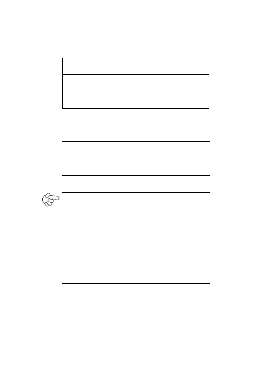
GPIO1:
(2.0mm Pitch 2x5 Pin Header), General-purpose input/output port, it provides
a group of self-programming interfaces to customers for flexible use.
Signal Name
Pin#
Pin#
Signal Name
Ground
1
2
NC
NC
3
4
SMB_DATA_R
SMB_CLK_R
5
6
SOC-GPIO22
SOC-GPIO23
7
8
SOC-GPIO25
SOC-GPIO24
9
10
+5V
USB_23:
(2.0mm Pitch 2x5 Pin Header), Front USB connector, it provides one USB port
via a dedicated USB cable, speed up to 480Mb/s.
Signal Name
Pin#
Pin#
Signal Name
5V_USB23
1
2
5V_USB23
USB3_N
3
4
USB2_N
USB3_P
5
6
USB2_P
Ground
7
8
Ground
NC
9
10
Ground
Note:
Before connection, make sure that pinout of the USB Cable is in accordance
with that of the said tables. Any inconformity may cause system down and
even hardware damages.
JP5:
(2.0mm Pitch 2x3 Pin Header), COM3 setting jumper, pin 1~6 are used to select
signal out of pin 9 of COM3 port.
JP5 Pin#
Function
Close 1-2
RI (Ring Indicator) (default)
Close 3-4
COM3 Pin9=+5V (option)
Close 5-6
COM3 Pin9=+12V (option)
COM3:
(Type DB9), serial port, standard DB9 serial port is provided to make a direct
connection to serial devices. COM3 port is controlled by pins No.1~6 of JP5,
select output Signal RI or 5V or 12v, for details, please refer to description of
JP5.