7 vmebus p2 connector (ipmc mode), Table 5-14, Vme p2 connector pinouts with ipmc712 – Artesyn MVME6100 Single Board Computer Installation and Use (June 2014) User Manual
Page 97: Vmebus p2 connector (ipmc mode), Pin assignments
Pin Assignments
MVME6100 Single Board Computer Installation and Use (6806800D58H)
97
The default configuration for P2, C27-C30 are connected to PMC0_IO (53,55,57,59).
5.2.7
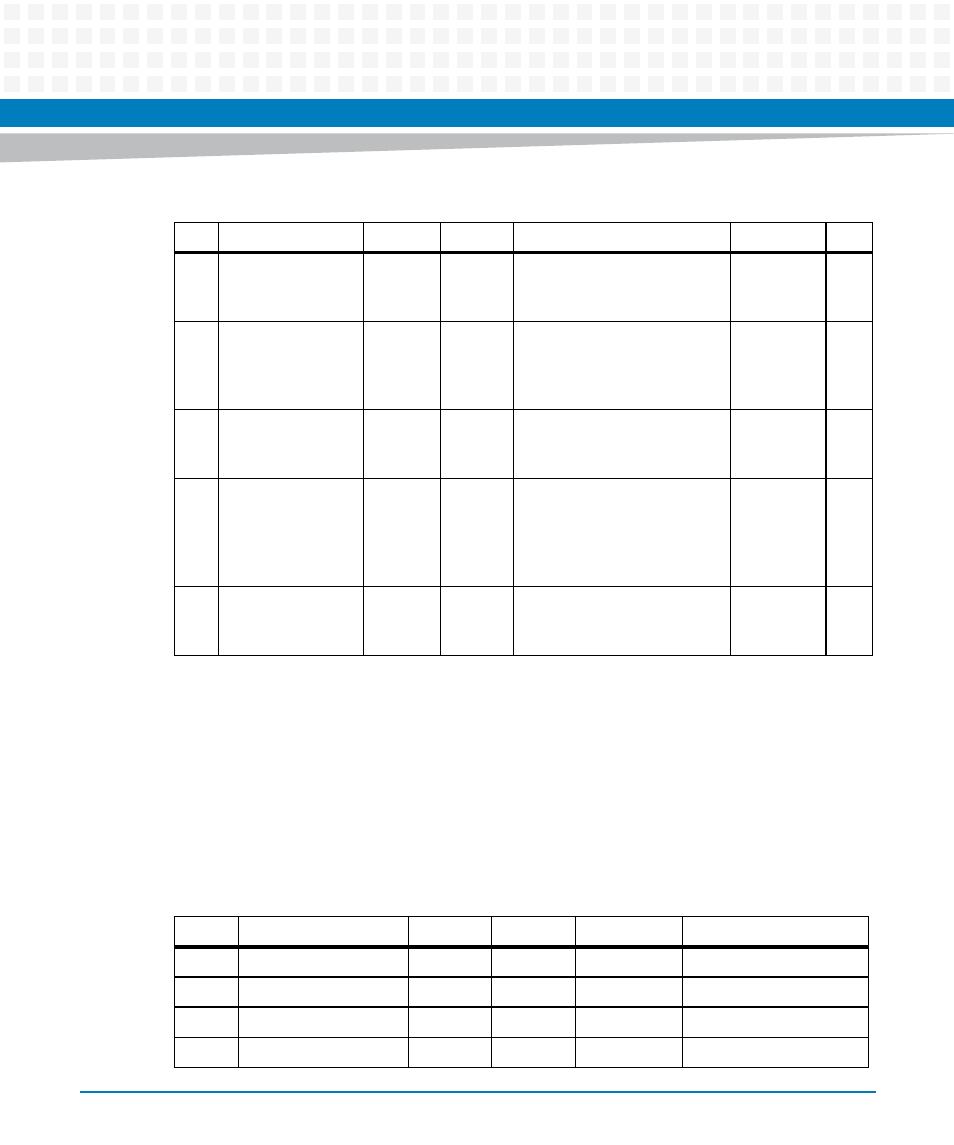
VMEbus P2 Connector (IPMC Mode)
The VME P2 connector is an 160-pin DIN. Row B of the P2 connector provides power to the
MVME6100 and to the upper eight VMEbus address lines and additional 16 VMEbus data lines.
The pin assignments for the P2 connector are as follows:
28
GND
PMC0_5
6 (J14-
56)
VD29
PMC0_55
(J14-55)/RXB
PMC1_42
(J24-42)
28
29
PMC1_44 (J30 D9-
C9) or
P2_IO_GLAN1_M
DIO_3- (J30 B9-C9)
PMC0_5
8 (J14-
58)
VD30
PMC0_57
(J14-57)/RTSB
PMC1_43
(J24-43)
29
30
GND
PMC0_6
0
(J14-60)
VD31
PMC0_59
(J14-59)/CTSB
PMC1_45
(J24-45)
30
31
PMC1_46 (J30
D10-C10) or
P2_IO_GLAN1_M
DIO_3+ (J30 B10-
C10)
PMC0_6
2 (J14-
62)
GND
PMC0_61
(J14-61)
GND
31
32
GND
PMC0_6
4 (J14-
64)
+5V
PMC0_63
(J14-63)
VPC
32
Table 5-13 VMEbus P2 Connector Pin Assignments (PMC Mode) (continued)
ROW Z
ROW A
ROW B
ROW C
ROW D
Table 5-14 VME P2 Connector Pinouts with IPMC712
Pin
Row Z
Row A
Row B
Row C
Row D
1
PMC2_2
DB0#
+5V
RD-
PMC2_1 (J24-1)
2
GND
DB1#
GND
RD+
PMC2_3 (J24-3)
3
PMC2_5
DB2#
N/C
TD-
PMC2_4 (J24-4)
4
GND
DB3#
VA24
TD+
PMC2_6 (J24-6)