Bypass damper connections, Figure 9: existing ez zone bypass damper wiring – Auto-Zone Control Systems EZ-Zone to Auto-Zone Upgrade Guide (Version 01C) User Manual
Page 22
EZ Zone/Auto-Zone
22
Upgrade
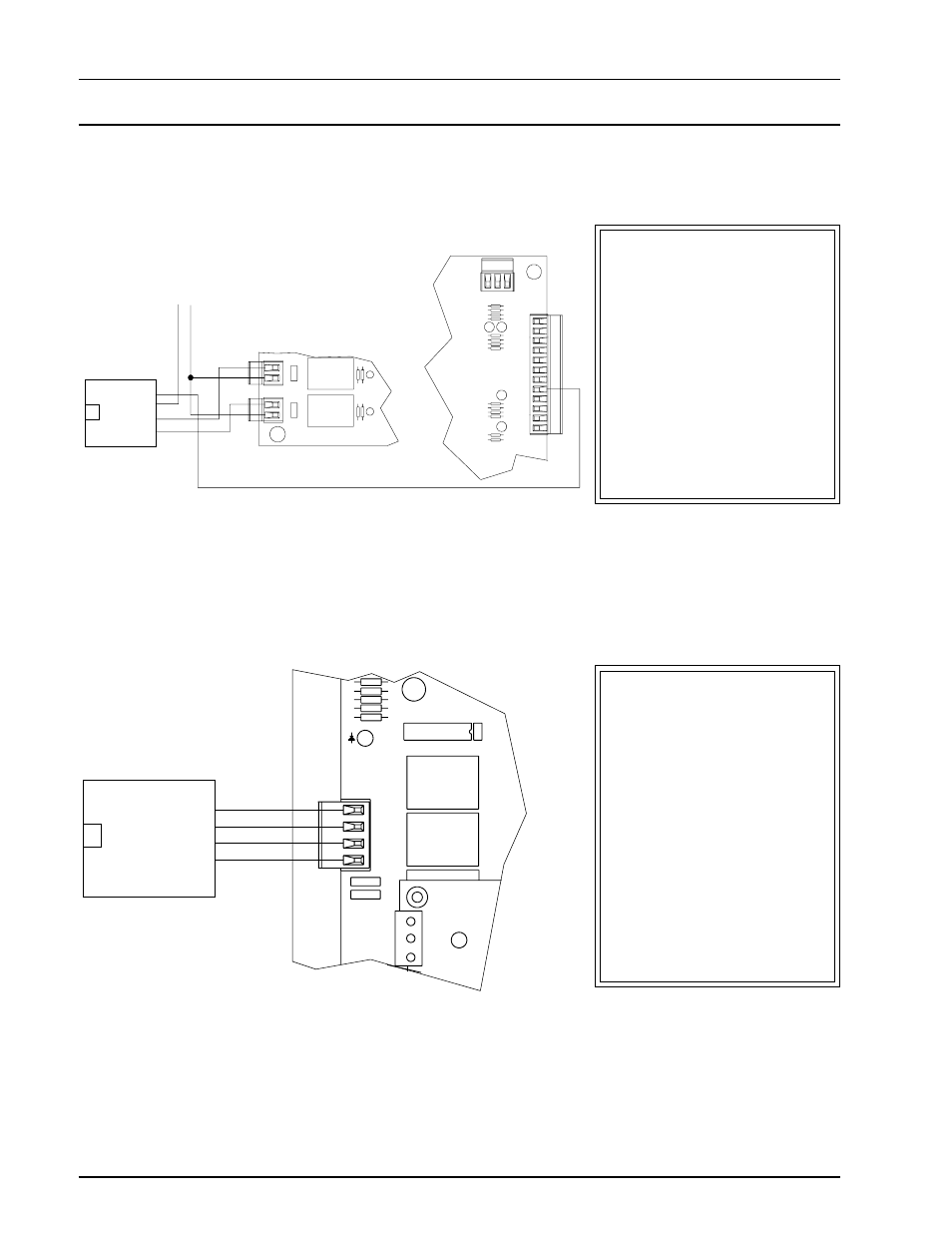
Figure 10: New Auto-Zone Bypass Damper Wiring
ANALOG
INPUTS
+V
+V
1
2
3
4
5
6
7
8
G
G
PRESSURE
SENSOR
+5V
SIG
GND
TB12
OUT6
OUT7
BYPASS
OPEN
BYPASS
CLOSE
Feedback
Gnd
Open
Close
Actuator Wiring
Interface
24 VAC
V4
V3
REC
CLOSE
OPEN
K1
K2
NETWORK
SH
R
T
NE5090
FDBK
GND
OPEN
CLOSE
Feedback (Bk)
Ground (Wh)
Open (Yl)
Close (Gr)
Actuator Interface
Wiring
Figure 9: Existing EZ Zone Bypass Damper Wiring
The EZ Zone Master Con-
troller has two double pole
terminal blocks for the by-
pass actuator connections.
These terminal blocks must
be tied together by an exter-
nal jumper. In addition, the
feedback connection from the
actuator must be terminated
on the other side of the con-
troller .
The Auto-Zone Zone Man-
ager wiring has been simpli-
fied. There is only one termi-
nal block with connections
clearly marked for ease of
installation. The actuator
“feedback” connection is
now terminated at the same
location as all the connec-
tions. Jumpers are no longer
required since the commons
are tied together within the
circuit board.
Bypass Damper Connections