Signal, Connector description, Power supply – BECKHOFF C9900-A172 User Manual
Page 7: Usb data transfer, Usb input, Dvi input (digital visual interface), Dvi data transfer
Product Description
Pin
Signal
Pin
Signal
1
Rx2-
13
Rx3+
2
Rx2-
14
+ 5V DVI
3
GND
15
GND
4
Rx4-
16
HPD
5
Rx4+
17
Rx0-
6
DDC CLK
18
Rx0+
7
DDC DAT
19
GND
8
AV SYNC
20
Rx5-
9
Rx1-
21
Rx5+
10
Rx1+
22
GND
11
GND
23
RxC+
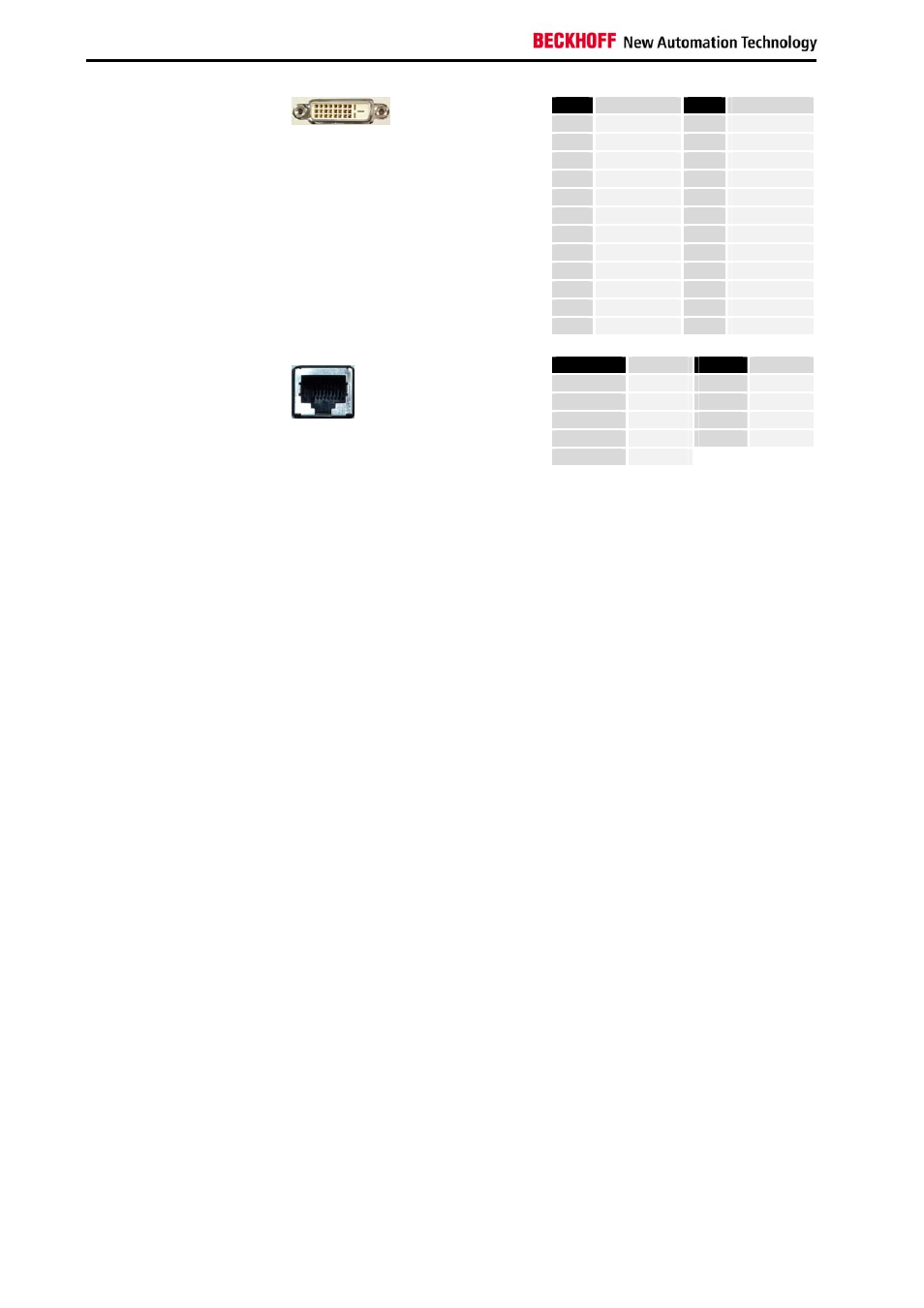
X 103
DVI-D In
DVI-D 3 X 8-pole digital
(MOLEX 74320-9000 / 74320-9004)
12
Rx3-
24
RxC-
Pin
Signal
Pin
Signal
Housing
Screen
5
n.c.
1
TD +
6
RD -
2
TD -
7
n.c.
3
RD +
8
n.c.
X 104
DVI Extension
RJ-45 connector (Ethernet 10/ 100 Mbit)
4
n.c.
Connector description
Power supply
Power supply
The cage clamp socket (X 100) is used to supply power to the DVI/USB
extension.
USB data transfer
USB Extension
The USB extension connection (X 101) is used for transferring the USB
signal from the transmitter module to the receiver module.
USB input
USB Upstream
The USB1.1 input (X 102) is used to connect the transmitter module with
the Industrial PC.
USB1.1 standard with a maximum data rate of 1.5 or 12 Mbps is
supported.
DVI input (Digital Visual Interface)
DVI-D In
The DVI connection (X 103) is used for transferring the video signal from
the Industrial PC to the transmitter module.
The purely digital part (DVI-D) is supported.
DVI data transfer
DVI Extension
The DVI extension connection (X 104) is used for transferring the DVI
signal from the transmitter module to the receiver module.
6
DVI/USB extension C9900-A17x