Transmitter plug-in card connections, Pin assignment, Signal – BECKHOFF C9900-A172 User Manual
Page 8
Product Description
Transmitter plug-in card connections
Connections for the
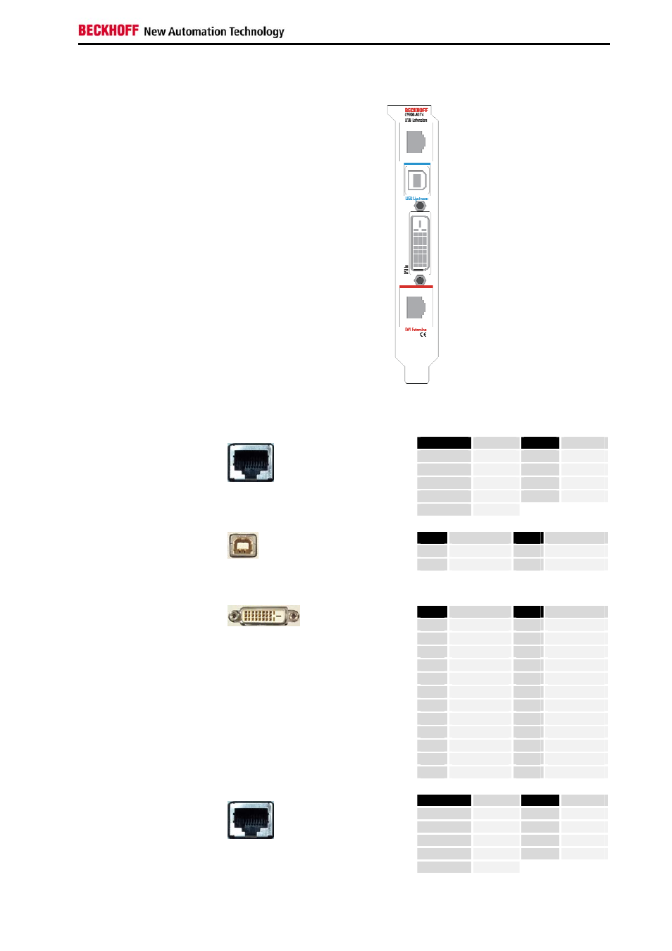
C9900-A174
PCI bus transmitter plug-in
card
X 100
X 101
X 102
X 103
Pin assignment
Pin
Signal
Pin
Signal
Housing
Screen
5
n.c.
1
TD +
6
RD -
2
TD -
7
n.c.
3
RD +
8
n.c.
X 100
USB Extension
RJ-45 connector (Ethernet 10/ 100 Mbit)
4
n.c.
Pin
Signal
Pin
Signal
1
5V
3
D+
2
D-
4
GND
X 101
USB Upstream
USB PCB-installation B-Type
(FCI 61729-0010B USB Receptacle B-Type)
Pin
Signal
Pin
Signal
1
Rx2-
13
Rx3+
2
Rx2-
14
+ 5V DVI
3
GND
15
GND
4
Rx4-
16
HPD
5
Rx4+
17
Rx0-
6
DDC CLK
18
Rx0+
7
DDC DAT
19
GND
8
AV SYNC
20
Rx5-
9
Rx1-
21
Rx5+
10
Rx1+
22
GND
11
GND
23
RxC+
X 102
DVI-D In
DVI-D 3 X 8-pole digital
(MOLEX 74320-9000 / 74320-9004)
12
Rx3-
24
RxC-
Pin
Signal
Pin
Signal
Housing
Screen
5
n.c.
1
TD +
6
RD -
2
TD -
7
n.c.
3
RD +
8
n.c.
X 103
DVI Extension
RJ-45 connector (Ethernet 10/ 100 Mbit)
4
n.c.
DVI/USB extension C9900-A17x
7