Mechanical construction – BECKHOFF BK5200 User Manual
Page 12
Basic Principles
12
BK52x0
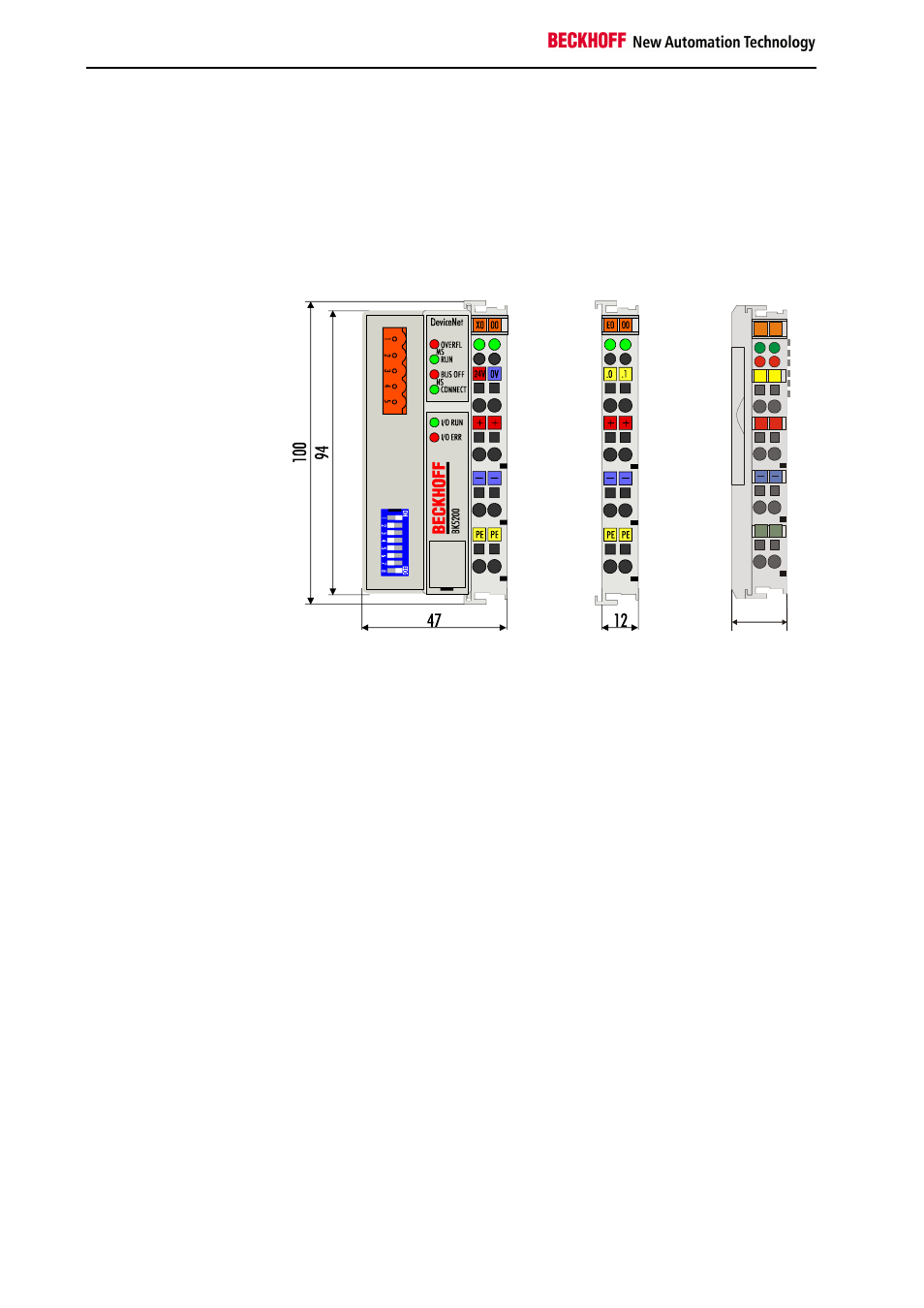
Mechanical construction
The system of the Beckhoff Bus Terminals is characterised by low physical
volume and high modularity. When planning a project it must be assumed
that at least one Bus Coupler and a number of Bus Terminals will be used.
The mechanical dimensions of the Bus Couplers are independent of the
fieldbus system.
Bus Coupler dimensions
02
01
+ +
S
S
C+
C-
00
X0
LC5100
Beckhoff
21
The total width in practical cases is composed of the width of the Bus
Coupler with the bus end terminal and the width of the Bus Terminals in
use. Depending on function, the Bus Terminals are 12 or 24 mm wide. The
front wiring increases the total height of 68 mm by about 5 to 10 mm,
depending on the wire thickness.
Assembly and connection
The Bus Coupler and all the Bus Terminals can be clipped, with a light
press, onto a 35 mm C-mounting rail. A locking mechanism prevents the
individual housings from being pulled off again. For removal from the
mounting rail the orange coloured tension strap releases the latching
mechanism, allowing the housing to be pulled off the rail without any force.
Work should only be carried out on the Bus Terminals and the Bus Coupler
when switched off. Pulling out and inserting under power can cause
undefined states to be temporarily caused. (A reset of the Bus Coupler, for
example.)
Up to 64 Bus Terminals can be attached to the Bus Coupler on the right
hand side. When plugging the components together, be sure to assemble
the housings with groove and tongue against each other. A properly
working connection can not be made by pushing the housings together on
the mounting rail. When correctly assembled, no significant gap can be
seen between the attached housings.
The right hand part of the Bus Coupler can be compared to a Bus
Terminal. Eight connections on the top permit connection with solid or fine
wires. The connection is implemented with the aid of a spring device. The
spring-loaded terminal is opened with a screwdriver or rod, by exerting
gentle pressure in the opening above the terminal. The wire can be
inserted into the terminal without any force. The terminal closes
automatically when the pressure is released, holding the wire securely and
permanently.