Introduction kl2612, Functional description, Power contact signal - led1 signal - led2 pe – BECKHOFF KL2612 User Manual
Page 2: Out in out out in
Datasheet for KL2612, Version 1.1
Beckhoff™ and TwinCAT are registered trademarks of Beckhoff. Information is subject to change without notice and warranted only to the extent agreed in the terms
of contract. Beckhoff Automation GmbH, Eiserstr. 5, 33415 Verl, Germany, Phone: +49 (0) 5246 963 0, Fax.: +49 (0) 5246 963 149,
http://www.beckhoff.com
Introduction KL2612
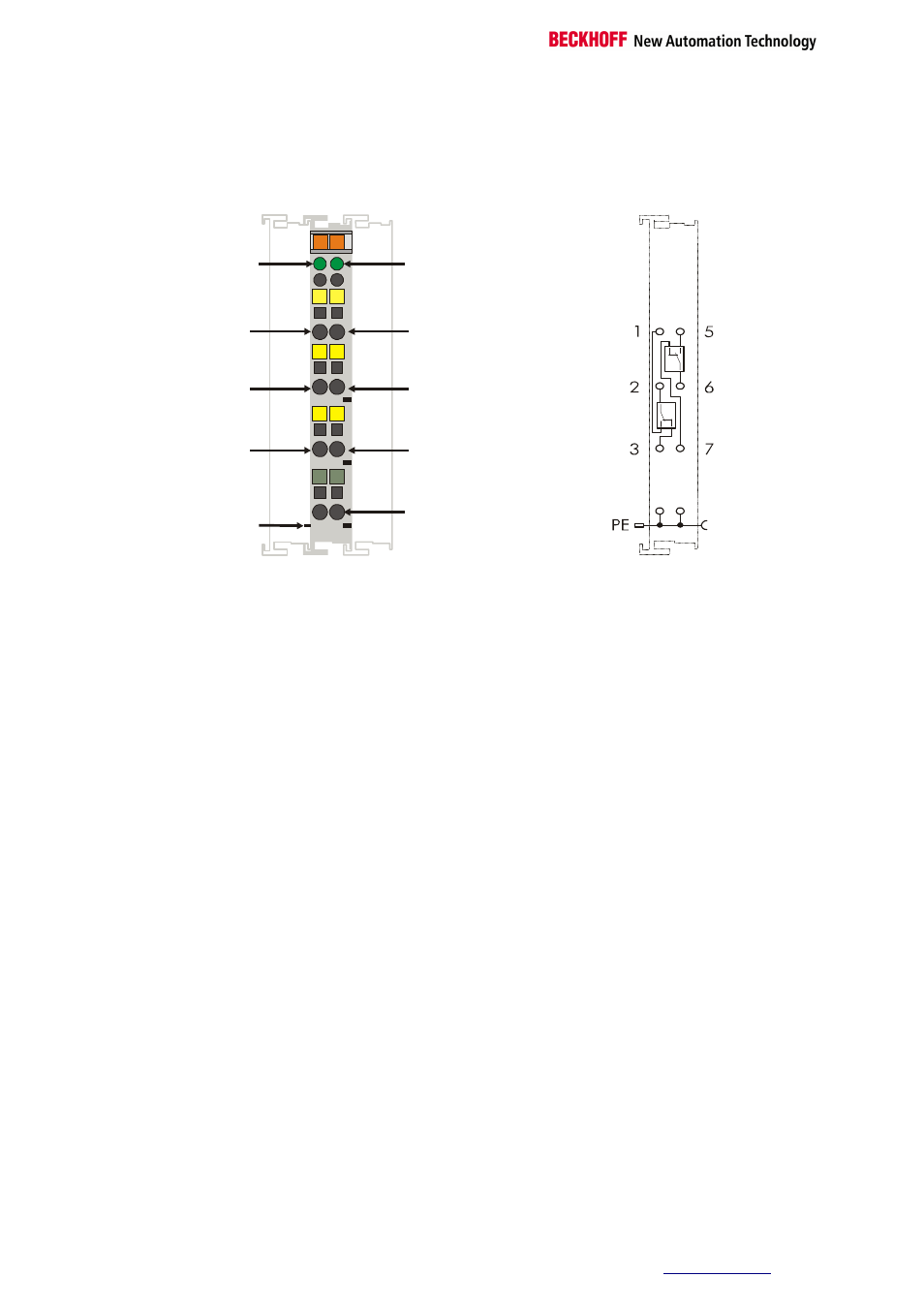
Top view
power
contact
Signal -
LED1
Signal -
LED2
PE
13
1
2
6
PE
14
5
PE
5
C
D
6
7
8
1
A
B
2
3
4
KL2612
3
7
OUT
OUT
IN
OUT
OUT
IN
Functional Description
The KL2612 output terminal switches two relays, each having one
changeover contact, under control of the automation device. The signal
state of the bus terminal is indicated by an LED. If the LED is on, it means
that the contact between 2 and 1 or, in the case of the second relay,
between 6 and 5, is closed. The KL2612 Bus Terminal does not have a
power contact, which means that a voltage that has been passed on
through earlier terminals via the power contacts must be fed in again after
a KL2612.
LED display
The signal LEDs indicate the operational state of the associated terminal
channel.
On:
Changeover between 2-1 (6-5) closed
Off:
Changeover between 2-3 (6-7) closed
Or:
A watchdog timer overflow has occurred. If no process data is handled by
the bus coupler for 100 ms, the green LED goes out and the outputs are
set to 0.
Process data
The bit-width in the process image is 2 bits.