Terminal configuration – BECKHOFF KL3351 User Manual
Page 7
Terminal configuration
KL3351
7
Terminal configuration
The terminal can be configured and parametrized by way of the internal
register structure.
Each terminal channel is mapped in the bus coupler. The terminal’s data is
mapped differently in the bus coupler’s memory depending on the type of
the bus coupler and on the set mapping configuration (eg.Motorola / Intel
format, word alignment,...). For parametrization of a terminal, the control
/status byte must also be mapped.
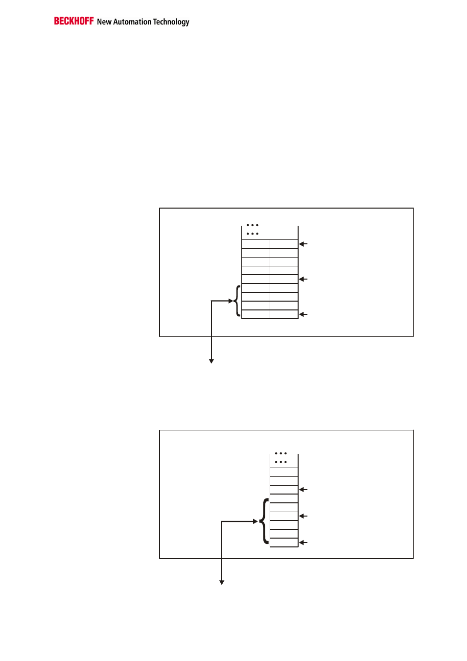
Beckhoff Lightbus
Coupler BK2000
In the case of the Beckhoff Lightbus coupler BK2000, the control /status
byte is always mapped besides the data bytes. It is always in the low byte
at the offset address of the terminal channel.
0
Offset Terminal1 Channel1 = 0
Offset Terminal2 Channel1 = 4
KL3351
Offset Terminal2 Channel2 = 8
User data allocation depending
on mapping
K-Bus
Beckhoff-Lightbus
bus coupler
BK2000
To the bus terminal
L
H
C/S - 0
D0 - 0
D0 - 1
D1 - 0
D1 - 1
C/S - 1
C/S
C/S
Data L
Data H
Data H Data L
C/S
The terminal is
mapped in the
bus coupler.
Profibus Coupler BK3000
In the case of the Profibus coupler BK3000, for which terminal channels
the control /status byte is also to be inserted must be defined in the master
configuration .If the control /status byte is not evaluated, the KL3351
occupies 4 bytes of input data (2 bytes of user data per channel).
Offset Terminal1 Channel1 = 0
Offset Terminal1 Channel2 = 3
Offset Terminal2 Channel1 = 6
KL 3351 Channel1
KL 3351 Channel 2
The control-/status byte
must be inserted for
parameterization.
K-Bus
Profibus bus coupler
BK3000
To the bus terminal
Data H
Data L
D1 - 0
D0 - 0
D0 - 1
D1 - 1
C/S - 0
C/S
C/S - 1
0
The terminal is
mapped in the
bus coupler.