BECKHOFF KL3351 User Manual
Page 9
Register description
KL3351
9
Internally, all intelligent terminals possess a data structure that is identical
in terms of it’s essential characteristics. This data area is organized in
words and embraces 64 memory locations. The essential data and
parameters of the terminal can be read and adjusted by way of the
structure. Function calls with corresponding parameters are also possible.
Each logical channel of an intelligent terminal has such a structure
(therefore, 4-channel analog terminals have 4 register sets.
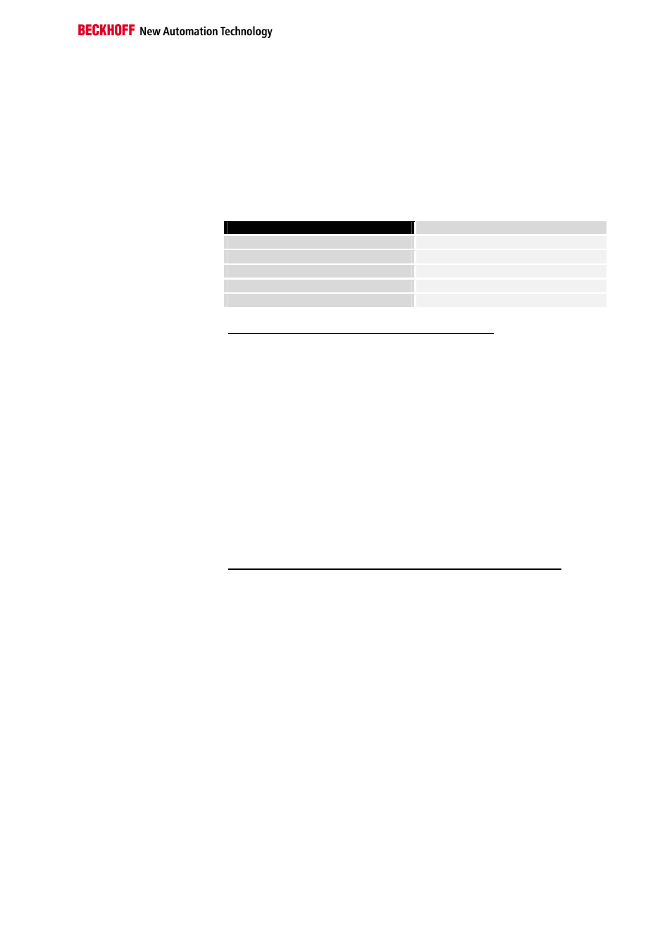
This structure is broken down into the following areas:
(You will find a list of all registers at the end of this documentation).
Area
Address
Process variables
0-7
Type registers
8-15
Manufacturer parameters
16-30
User parameters
31-47
Extended user area
48-63
Process variables
R0 – R7: Registers in the terminal’s internal RAM:
The process variables can be used in additional to the actual process
image and their functions are specific to the terminal.
R0 – R5: These registers have a function that depends on the terminal
type.
R6: Diagnostic register
The diagnostic register may contain additional diagnostic information. In
the case of serial interface terminals, for example, parity errors that have
occurred during data transfer are indicated.
R7: Command register
High-Byte_Write = function parameter
Low-Byte _Write = function number
High-Byte _Read = function result
Low-Byte_ Read = function number
Type registers
R8 – R15 Registers in the terminal’s internal ROM der Klemme
The type and system parameters are programmed permanently by the
manufacturer and can only be read by the user but cannot be modified.
R8: Terminal type:
The terminal type in register R8 is needed to identify the terminal.
R9: Software version X.y
The software version can be read as an ASCII character string.
R10: Data length
R10 contains the number of multiplexed shift registers and their length in
bits.
The bus coupler sees this structure.
R11: Signal channels
In comparison with R10, the number of logically existing channels is
located here. For example, one physically existing shift register may
consist of several signal channels.
R12: Minimum data length
The respective byte contains the minimum data length of a channel to be
transferred. If the MSB is set, then the control/status byte is not necessarily
needed for the function of the terminal and, with appropriate configuration
of the coupler, is not transferred to the control system.