Mounting positions and distances, Electrical installation, Cables – BECKHOFF AX2090-BW5x User Manual
Page 3
Page 3/4
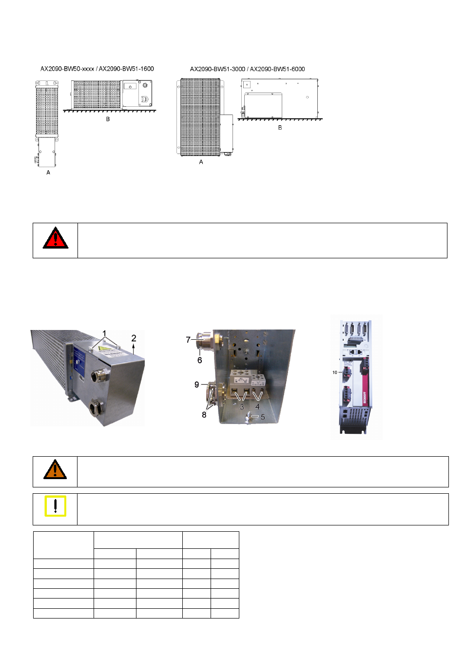
Mounting positions and distances
(A) = vertical installation is only permitted according to the diagram (terminal box facing downwards).
(B) = horizontal installation
For all mounting positions the following minimum distances must be adhered to:
200 mm to adjacent components, walls etc. and 300 mm to components, ceilings etc. above. If the device is installed vertically (A), the minimum
distance to components, floors etc. below is 200 mm in order to allow unobstructed flow of air to the brake resistor.
Electrical installation
DANGER
Caution – Danger of death!
Disconnect the AX5000 from the mains before installing the brake resistor!
Even when the AX5000 is disconnected from the mains voltage, dangerous voltage continues to be present at the "X02" terminals
of the DC link for at least 5 minutes. Never touch the terminals within this period.
Remove the two screws (1) and remove the cover (2) in direction of the arrow. Connect an adequately dimensioned cable (see section Cables) to
the terminals (3) of the resistor and the earthing stud (5) and take it out of the terminal box through the strain-relief assembly (9). Ensure adequate
strain relief with the two screws (8). Connect the other side of the cable to the DC link contact connector X2 (10) of the AX5000. The connector is
supplied with the AX5000. Connect the earthing cable to the earthing conductor of the control cabinet.
Connect an adequately dimensioned cable to the potential-free N/C contact (4) of the temperature switch and take it out of the terminal box through
the strain-relief assembly (7) (see section Temperature switch). Ensure adequate strain relief with the nut (6).
Install the cover (2) in reverse order.
Cables
We recommend Beckhoff motor cables for connecting the brake resistors.
WARNING
Caution - Fire hazard!
The brake resistors become very hot. Only use cables with adequate heat resistance.
Warning
EMC safety
Use only shielded cables.
Brake resistor
Temperature
switch
Type
[mm
2
] [AWG]
[mm
2
] [AWG]
AX2090-BW50-0300 1,5
16
0,75 18
AX2090-BW50-0600 1,5
16
0,75 18
AX2090-BW50-1600 1,5
16
0,75 18
AX2090-BW51-1000 2,5
12
0,75 18
AX2090-BW51-3000 2,5
12
0,75 18
AX2090-BW51-6000 2,5
12
0,75 18
We recommend wire end sleeves.