Temperature switch, Short-term capacity, Duty cycle – BECKHOFF AX2090-BW5x User Manual
Page 4: Overload factor, Calculation formula
Page 4/4
Temperature switch
Warning
Destruction of the brake resistor
The temperature switch is only used for temperature
monitoring. The brake resistor is not switched off.
The temperature switch has a potential-free N/C contact, which enables
immediate response to any overload of the brake resistor through analysis in
the AX5000 or the PLC. Connect the cable directly to a free input of plug "X06".
Then parameterise it such that the AX5000 stops the motor(s) with an
emergency ramp or the PLC reads and processes this input.
Short-term capacity
Brake resistors are usually not operated continuously, but only exposed to short-time duty. In the following section the permitted short-term capacity
is calculated based on the continuous power, overload factor and duty cycle.
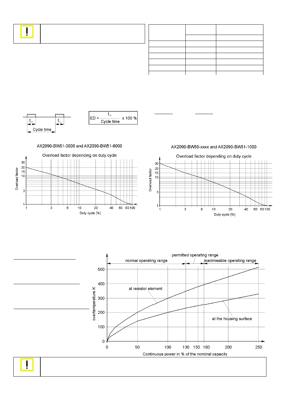
Duty cycle
The duty cycle is a relative value that depends on the switch-on time (t
on
)and the cycle time. Cycle times up to 120 sec. are used directly in the
calculation. Should the cycle time exceed 120 sec., the maximum relevant cycle time of 120 sec. is used in the calculation.
Overload factor
Calculation formula:
Short-term capacity = continuous power x overload factor
Overtemperature and continuous power at 100% duty cycle
If your application requires a higher continuous power than the specified nominal capacity, you can accept this state if a higher brake resistor
temperature is permitted. The following diagram shows the overtemperature v. the continuous power.
Normal operating range, max. 130%:
This operating range is recommended for
maximum service life and error-free
operation.
Permitted operating range, max. 160%:
This operating range is still permitted,
although it results in shorter service life with
higher failure probability.
Inadmissible operating range, more than 160%:
In this operating range there is a risk of
destruction of the brake resistor through
overheating. Due to the high temperatures
the adjacent components are also at risk.
Warning
Destruction of the brake resistor and adjacent components
Always ensure adequate ventilation of the brake resistor, since the temperatures of the housing surface may exceed 200 °C.
Example 1 Example
2
t
on
= 60 s
t
on
= 40 s
Cycle time = 280 s
Cycle time = 100 s
Duty cycle = 50 %
Duty cycle = 40 %
Switching
temperature
Switching current
24 VDC or 230 VAC
Type
[°C] [A]
AX2090-BW50-0300
180 2
AX2090-BW50-0600
180 2
AX2090-BW50-1600
180 2
AX2090-BW51-1000
180 2
AX2090-BW51-3000
85 2
AX2090-BW51-6000
85 2