Rear panel diagram – Bolide SVR8000s User Manual
Page 15
SVR-8000S User’s Manual
15
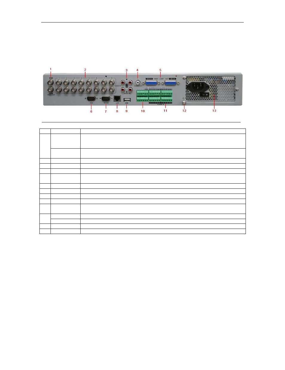
Rear Panel Diagram
Take SVR-8000S for illustration:
Figure 7. Rear Panel Diagram
No.
Item
Description
1
VIDEO OUT
BNC connector for video output. If VGA is connected, the interface will not function. If VGA
is not connected, the interface is used as the main video output with local video display and
menu operations.
VIDEO SPOT
OUT
BNC connector for monitor. Single window view.
2
VIDEO IN
BNC connectors for analog video input.
3
AUDIO IN
RCA connectors for analog audio input.
4
AUDIO OUT
RCA connector for audio output. This connector is synchronized with VIDEO OUT.
5
Video LOOP
OUT
16-ch DB15 connector for video loop out
6
VGA
VGA output. Display local video output and menu.
7
RS232
DB9 connector for RS232
8
LAN Interface
Connector for LAN (Local Area Network).
9
USB Interface
Connector for USB devices.
10
RS-485
Interface
Connector for RS-485 devices. T+, T- pin connects to PTZ.
Connector for KB devices. D+, D- pin connects to special keyboard.
11
ALARM IN
Connector for alarm input.
ALARM OUT
Connector for alarm output.
12
GROUND
Ground(needs to be connected when DVR startup)
13
POWER
AC 100~240V