3 power supply, 4 in/output signals – Bronkhorst E-5700 User Manual
Page 6
page 6
9.17.009
BRONKHORST HIGH-TECH B.V.
1.3 Power supply
Each E-5700 housing incorporates one power supply.
System setup in such that maximal 6 channels are available. The max. number of instruments depends on the
individual power requirement of each instrument.
The power input incorporates an on/off switch and a fuse. For extra protection the power supply has a separate
internal fuse.
1.4 In/output signals
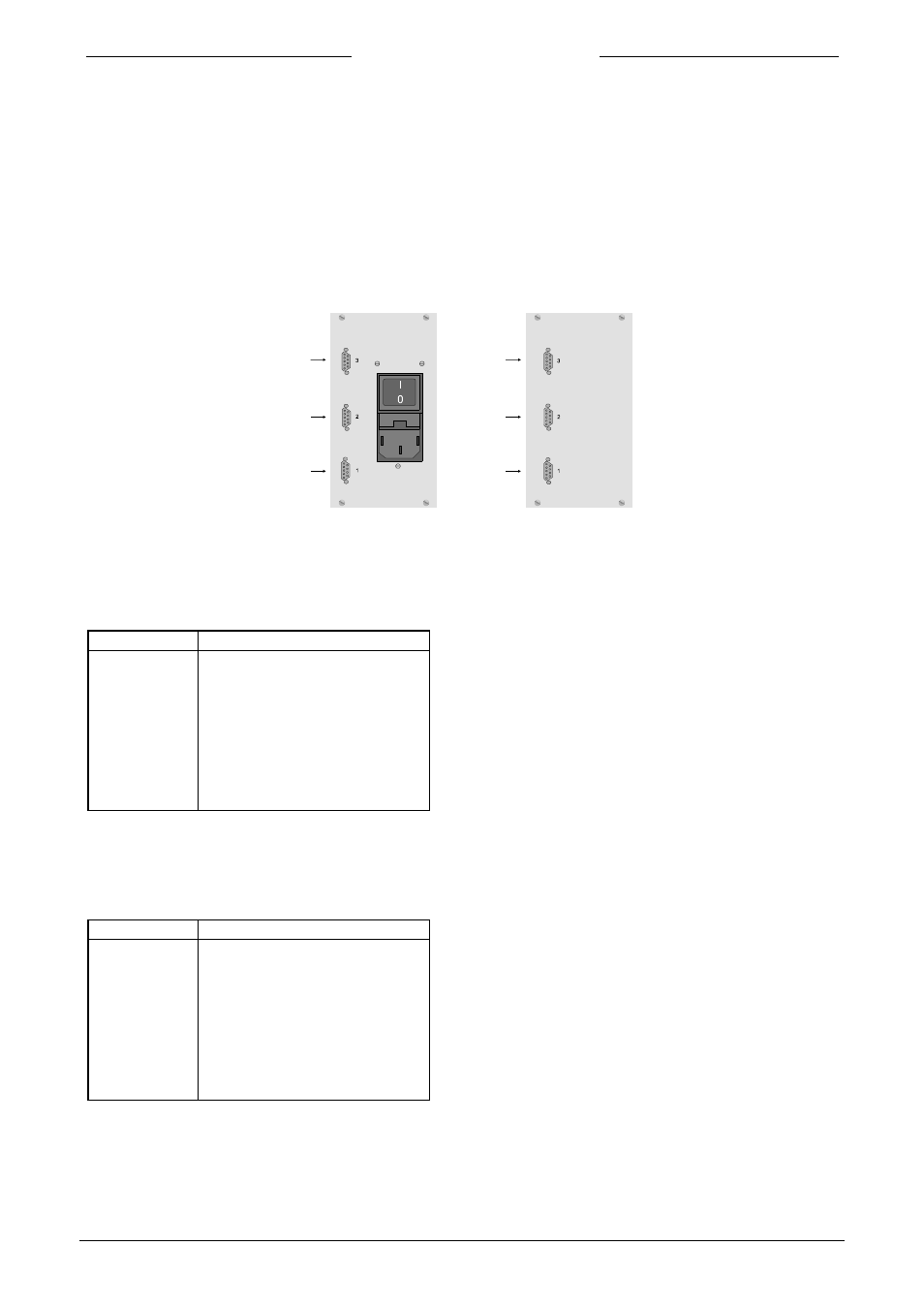
1.4.1 Rearpanel connectors
I/O
I/O
ch. 2
ch. 2
ch. 1
ch. 1
1.4.2 Connection to measuring and controlling devices
The instrument connectors 1 and 2 are female sub-miniature 9-pin D-connectors. The pin designation is
according to the BRONKHORST HIGH-TECH B.V. standard for analog instruments.
Pin number
description
1 not
used
2
0 - 5 (10) Vdc output signal
3
0 - 5 (10) Vdc setpoint signal
4 0
Valve
5 +
Valve
6
- 15 Vdc power supply
7
+ 15 Vdc power supply
8 0
V/common
9 ground/shield
1.4.3 Connection to remote equipment
The female in/out (sub-miniature 9-pin) D-connector 3 has the following pin configuration.
Pin number
description
1
Ext. output ch. 1
2
Ext. output ch. 2
3 not
used
4
Ext. input ch. 1
5
Ext. input ch. 2
6 not
used
7 not
used
8 0
V/common
9 ground/shield