Bronkhorst E-5700 User Manual
Page 7
9.17.009
page 7
BRONKHORST HIGH-TECH B.V.
1.4.3.1 Analog input/output signals
Analog input signals should be connected to pin 4 (+) for channel 1 and/or pin 5 (+) for channel 2 and
0 Vdc/common.
Analog output signals are available at pin 1 (+) for channel 1 and/or pin 2 (+) for channel 2 and 0 Vdc/common.
Signals are according to one of the Bronkhorst HIGH-TECH B.V. standards. The model configuration contains a
code, describing the input/output signals.
Notes:
a. Max. load current output : 300 Ohm (sourcing output)
b. Min. load voltage output: 10 kOhm
c. Input load resistance (voltage) 1 MOhm
d. Input load resistance (current) 61,4 Ohm (sinking input)
1.4.4 EMC and cables
The system setup described in this manual carries the CE-mark. Therefore it has to comply with the EMC
requirements as are valid for this kind of equipment.
However compliance with the EMC requirements is not possible without the use of proper cables and
connector assemblies.
For good results Bronkhorst HIGH-TECH B.V. can provide standard cables. Otherwise follow the guidelines as
stated below.
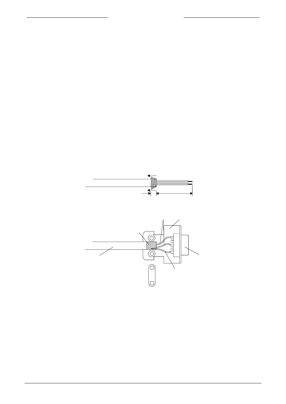
Fold the shield of the cable back over the cable (the shield must be around the cable).
Wind a copper tape around the shield
Solder a black wire on the tape and
connect to pin 9 of connector
copper tape
shielded cable
e.g. LAPP LiYCY
other wires
D-connector housing
metalized
connector
8 mm
20 mm
black wire
(shield)
Note:
When connecting the system to other devices (e.g. I/O to PLC), be sure that the integrity of the shielding is not
affected. Do not use unshielded wire terminals.