0 full range output - 3-way operation only, 0 led indicators – BSS Audio FDS-310 Owner's Manual User Manual
Page 21
21
15.0
Full range Output -
3-way operation only
When switched on 'MONO 3-WAY' mode, the Channel 2 input ('FULL
RANGE' in 3-way mode) is not wasted. Instead, it can be used as a balanced
in-out line driver passing through to the adjacent 'FULL RANGE' output
sockets. Follow the yellow legend for this.
In combination with the remainder of the FDS-310, it shares the following
facilities:
• Up to +6dB of gain.
• +6 to -00 gain adjustment, using the 'FULL RANGE' level trim control.
• Balanced or unbalanced drive into load impedances down to 600 ohms.
• Input filtration: -3dB down at 15Hz and 30kHz, see the main specification
in section 24.
Only the crossover filter slopes are disabled in 3-way mode. The 'FULL
RANGE' output retains MUTE and POLARITY switching, and PEAK and
SIGNAL present LED indication, as specified in section 16.
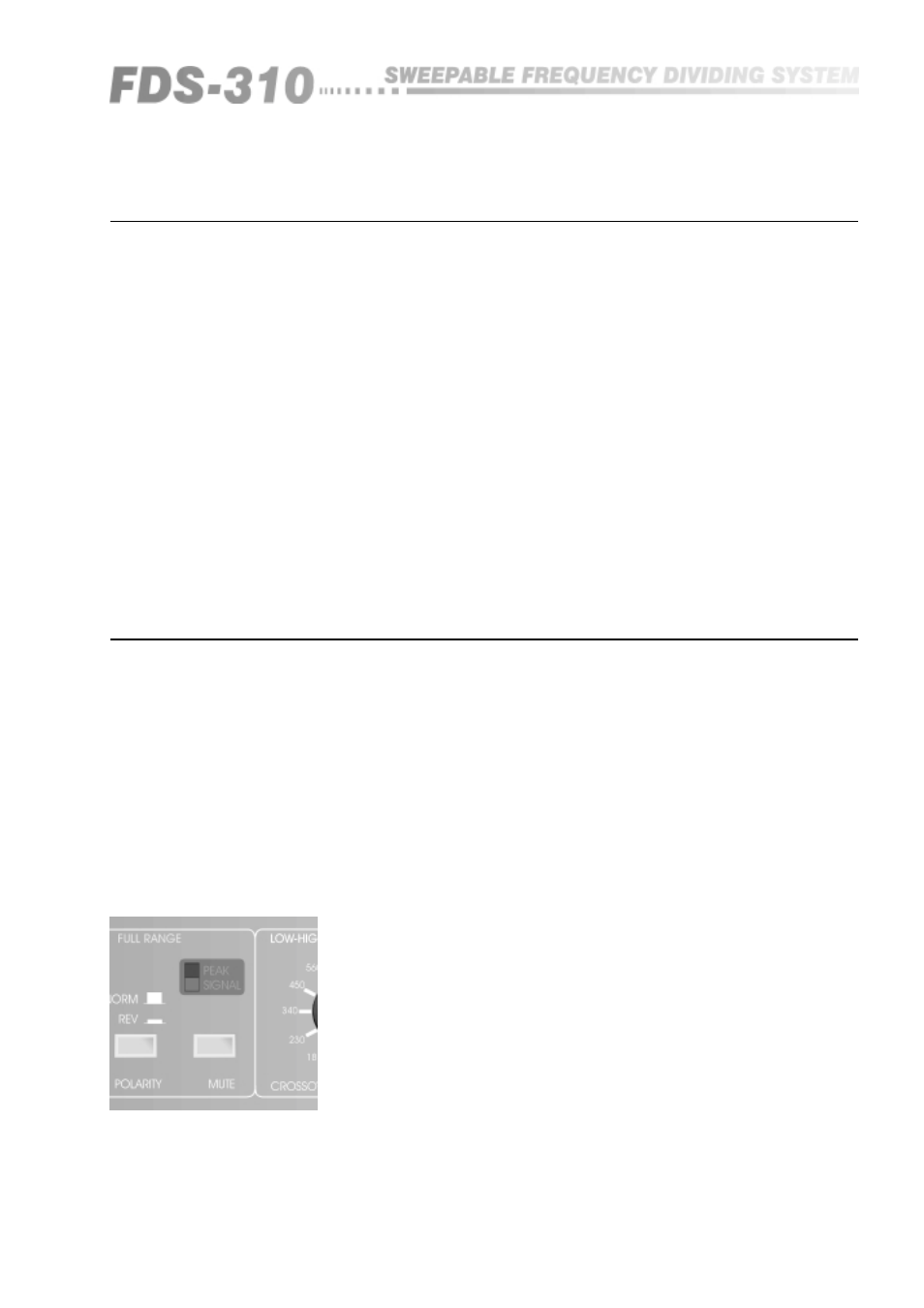
16.0
LED indicators
On each channel, the LED 'GREEN SIGNAL' lights to show that a signal is
being received. Steady illumination means high drive levels. Periodic flashing
indicates average drive levels. The LEDs will NOT LIGHT if the peak signal
level stays below -15dBu (138 millivolts).
On each channel, the red 'PEAK' LED lights if the internal signal levels of the
crossover approaches or exceeds overload. They will light at levels in excess
of +17dBu, giving a 3dB advance warning of actual overload and clip which
occurs at +20dBu .
The signal level appearing at the output sockets under these conditions will
depend on the level control position. However, most power amplifiers will be
driven hard into clip at levels in excess of +1dBu. Remember that clipped
output signals are the number one cause of damaged loudspeaker drive-units.
Under all normal conditions, and with a normal system gain-structure, the red
'PEAK' LED will NOT flash - EVER.
If the FDS-310 requires driving so hard that the 'PEAK' LEDs are periodically
lit up, we recommend that you investigate your system's gain structure,
particularly the power amplifiers sensitivity.
Fig 16.1 Peak and
Signal LEDs
16.2 'Peak'
16.1 'Signal
Present'
Full Range Output
LED Indicators