22 ....................ac power wiring diagram, Ac power wiring diagram, Electrical component chart – BUG-O Systems AGS-4000 User Manual
Page 22
Advertising
22
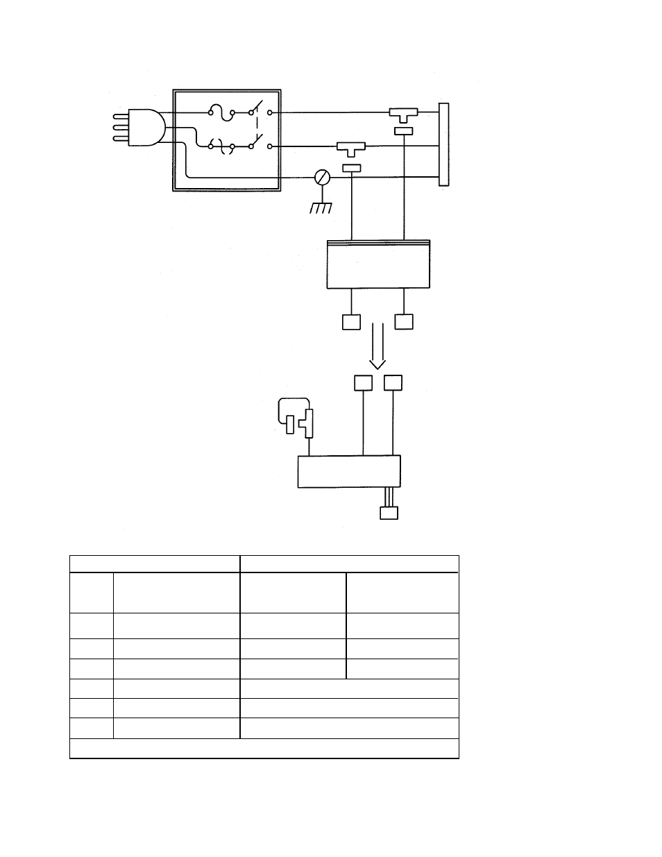
AC POWER WIRING DIAGRAM
PEM
BLK
RFI
RED
GRN
GRN
PC
J1
AC
POWER
OUT
BLK
RED
RED
BLK
120 VAC
&
240 VAC
BLK
RED
PS
BLU
DC OUT
ELECTRICAL COMPONENT CHART
MPD-1002 MPD-1004
ITEM DESCRIPTION
120 VAC
240 VAC
F1,F2* Fuses
(1) MPD-1026 2A (2) MPD-1027 3A
PC Power Cord
MPD-1001
MPD-1003
PS Power Supply
PCB-1005-120 PCB-1005-240
J1 Connector w/Pins
MPD-1021
PEM Power Entry Module
MPD-1025
RFI Filter Module
MPD-1008
PART NUMBER
FUSE BOX
F1
*F2
*F2 replaced with bus wire on 120 VAC
Advertising
This manual is related to the following products: