4 remote start of the psu – Cadac S-Type User Manual
Page 14
2-4
Connections and setup
S-Type
Revision S2005-6
51617
5HPRWH#VWDUW#RI#WKH#368
Each 8500 switch-mode power supply provides the following outputs: 13V, ±18V and
48V. Each PSU is fitted with a front panel mounted 9-way ‘D-type’ connector labelled
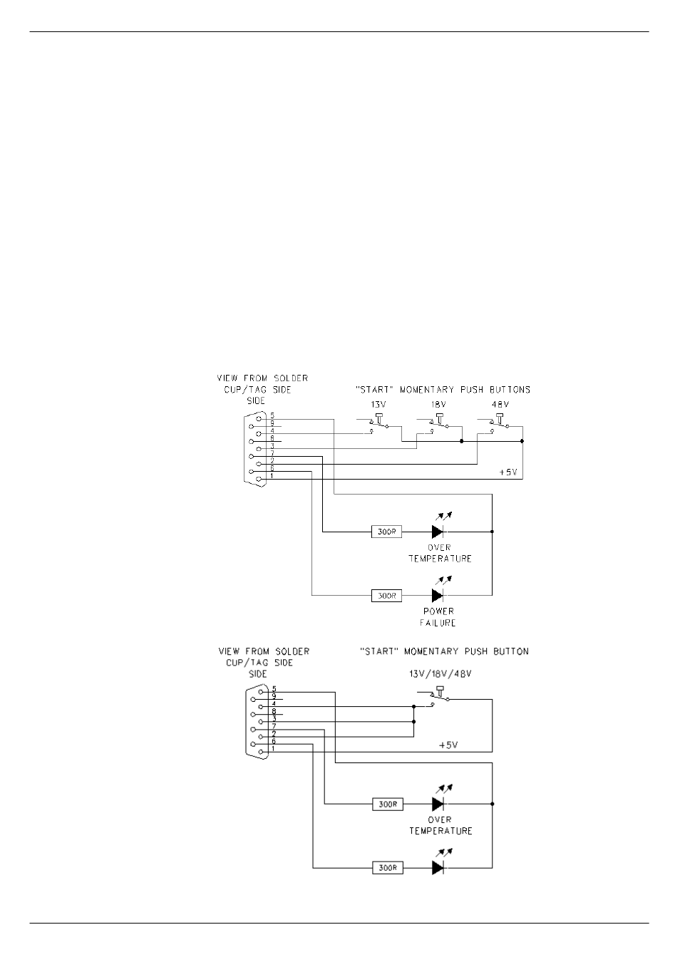
“Connections for Remote Start”. If a remote start facility is used, Power Failure and
Over-temperature LEDs may also be fitted with the remote start switches if required.
Fig 2-5 shows the circuit for starting up a ‘system’ with a single switch. This has
proved to be the most popular method of connecting the remote start facility. This cir-
cuit can easily be extended to provide a single switch for all PSUs if required. If mul-
tiple switches are to be used, see fig 2-4.
NOTE:
■
■
■
■
The remote start switch must be of a ‘momentary’ type. You can use 3 separate
single pole switches for each power supply to turn on 13V, ±18V and 48V outputs of
the PSUs alternatively use one single pole for the whole lot.
■
■
■
■
The remote switch(es) must be mounted on a metal panel.
■
■
■
■
Use shielded cable for the remote switch wiring.
■
■
■
■
The 9-way D-type free plug must have a conductive shell. This is to ensure that
the cable shield connects directly to the PSU unit chassis.
■
■
■
■
Connect the cable shield to the metal panel where the remote start switch(es)
are mounted.
FIG 2-4. Remote start with multiple switches
FIG 2-5. Remote start with a single switch