Connection of the power sup- ply cable – Caple C270GSS User Manual
Page 31
Advertising
31
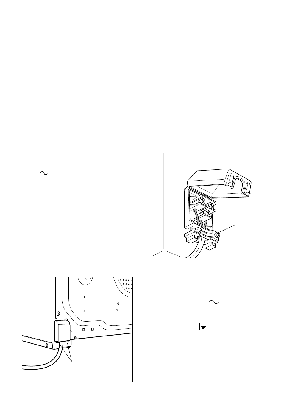
CONNECTION OF THE POWER SUP-
PLY CABLE
Unhook the terminal board cover by
inserting a screwdriver into the two
hooks “A” (fig. 11.1).
Open the cable gland by unscrewing
screw “F” (fig. 11.2), unscrew the termi-
nal screws and remove the cable.
The new supply cable, of suitable type
and section, is connected to the terminal
board following the diagram fig. 11.3.
FEEDER CABLE SECTION TYPE HO5RR-F
230 V
3 x 1,5 mm
2
Fig. 11.1
A
F
Fig. 11.2
230 V
PE
N
L
1
(L )
2
Fig. 11.3
Advertising
This manual is related to the following products: