Lubricating the gas taps, Regulating the burner minimum setting, Table for the choice of the injectors – Caple C762GSS User Manual
Page 15
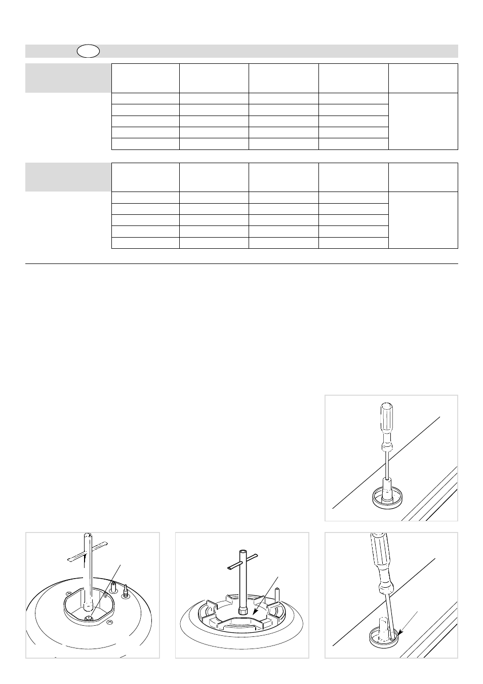
Fig. 5.6
A
Fig. 5.5
Fig. 5.4
J
Fig. 5.3
J
OPERATIONS TO BE PER-
FORMED WHEN SUBSTITU-
TING THE INJECTORS
To replace the injectors:
✓
Remove the gratings, the burner
covers and the knobs;
✓
Using a wrench substitute the nozzle
injectors “J” (Fig. 5.3 - 5.4) with those
most suitable for the kind of gas for
which it is to be used.
The burner are conceived in such a
way so as not to require the regulation
of the primary air.
LUBRICATING THE GAS
TAPS
If one of the gas taps becomes difficult to
turn, dismantle it, thoroughly clean with
petrol and apply special high-temperature
grease.
These operations must be performed by a
specialised engineer.
REGULATING THE BURNER
MINIMUM SETTING
When changing from one type of gas to
another, the minimum tap output must
also be correct, considering that in this
position the flame must be about 4 mm
long and must remain lit even when the
31
Cat:
II
2H3+
TABLE FOR THE CHOICE OF THE INJECTORS
Gas type:
G20
GB
Auxiliary (A)
1,00
0,30
72 (X)
Semi-rapid (SR)
1,75
0,45
97 (Z)
Rapid (R)
3,00
0,75
115 (Y)
Triple ring (TC)
3,50
1,50
135 (T)
Fish burner (PS)
2,95
1,50
120 (F3)
BURNERS
NOMINAL
POWER
(HS - kW)
REDUCED
POWER
(HS - kW)
Ø INJECTOR
(1/100 mm)
GAS
PRESSURE
(mbar)
20
Gas type:
G30/G31
Auxiliary (A)
1,00
0,30
50
Semi-rapid (SR)
1,75
0,45
65
Rapid (R)
3,00
0,75
85
Triple ring (TC)
3,50
1,50
95
Fish burner (PS)
2,95
1,50
85
BURNERS
NOMINAL
POWER
(HS - kW)
REDUCED
POWER
(HS - kW)
Ø INJECTOR
(1/100 mm)
GAS
PRESSURE
(mbar)
28-30/37
knob is turned sharply from the maximum
to the minimum position.
The adjustment is performed with the bur-
ner lit, as follows:
– Turn the knob to the minimum position.
– Remove the tap knob.
On gas valves provided with adjust-
ment screw in the centre of the shaft
(fig. 5.5):
✓
Using a screwdriver with max.
diameter 3 mm, turn the screw inside
the tap until the correct setting is
obtained.
On gas valves provided with adjust-
ment screw on the valve body (fig. 5.6):
✓
Turn the screw “A” to the correct
setting with a screwdriver.
✓
In models with a gas-lighter
incorporated into the knob, turn screw
“A” via the hole in the microswitch.
For G 30/G 31 gas, tighten the adjust-
ment screw completely.