CHIAYO QR-2000N User Manual
Page 4
-3-
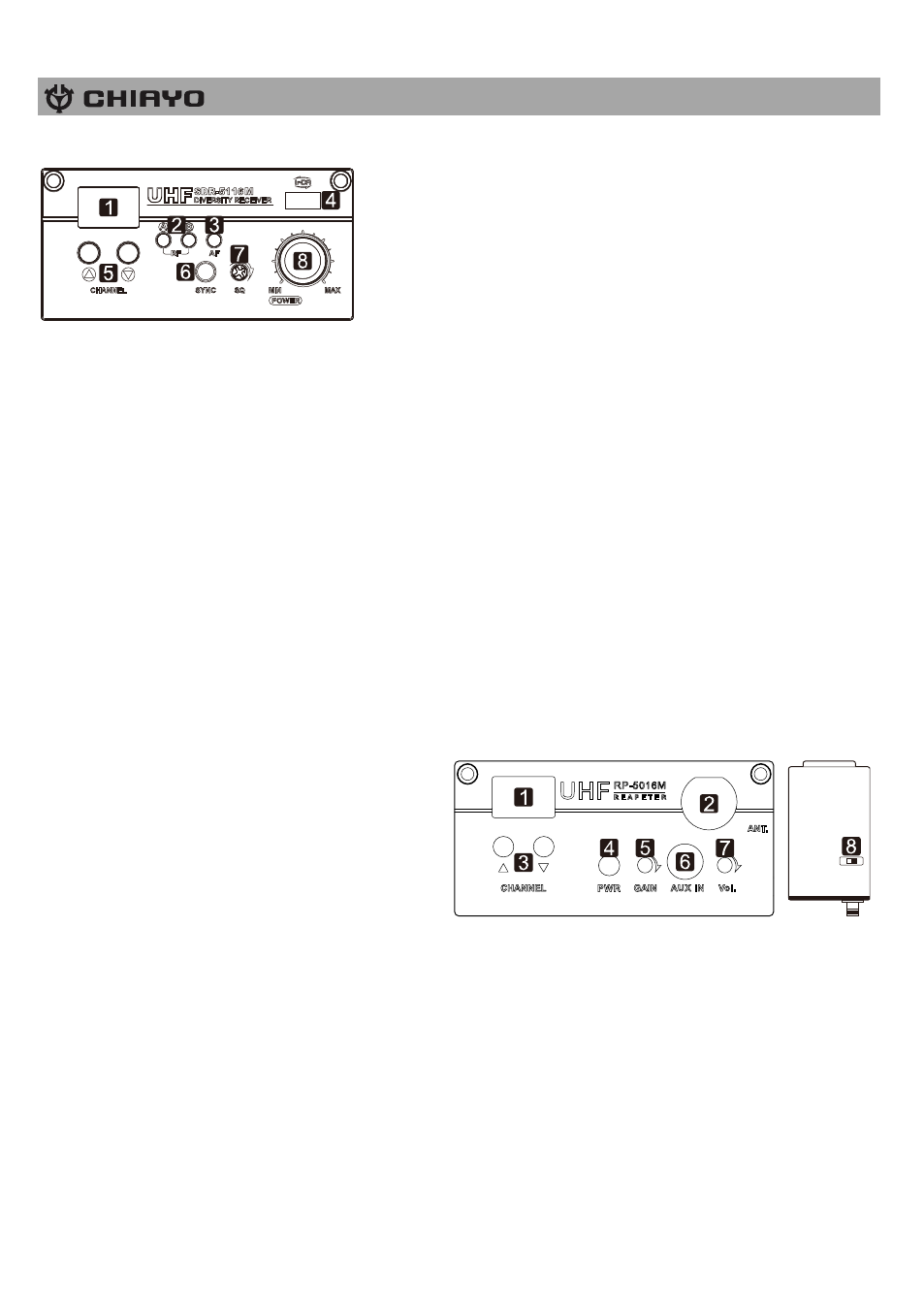
SDR-5200M IrDA|SDR-5100M receiver modules
1. Channel indicator
2. Diversity A/B indicator
3. Audio signal indicator
4. IR sensor area
5. Channel Selector
6. IRDA synchronizing button
7. Squelch control
8. Power switch/volume
control
First turn on the Power of the main unit. Then turn on the individual power of the receiver
module. Select a channel that corresponds to the transmitter. When transmitter is turned on,
either A or B diversity indicator will flash to indicate that signal has been received.
SQUELCH (SQ) setting
When a channel is in use and undesired interference signal is received, turn the SQ in
clockwise direction to make the receiver less sensitive and thus less susceptible to interference.
If this still does not solve the problem, it means this frequency is not applicable at current
position. Please switch over to the next channel.
Channel synchronizing of the receiver and transmitter
1. To achieve a trouble-free synchronization, please limit the distance between the receiver and
transmitter to within 30cm.
2. Align both sensor areas
3.
To change the receiver’s channel, please press the synchronizing button of the transmitter.
The transmitter will transmit synchronizing signal to the receiver and change its channel.
4. To change the transmitter
’s channel, please press the synchronizing button of the receiver.
The receiver will transmit synchronizing signal to the transmitter and change its channel.
RP-5100M
transmitter module
This unit should be installed in the Master
unit as a Repeater Transmitter to perform
wireless link with the Slave unit.
1. Channel indicator
2. Antenna socket(TNC type)
3. Channel selectors: Press ▲(up)▼(down)
to increase/decrease channel number. Please select a non-interfering frequency channel to
those already used in the master unit receiver modules. For wireless link to work, the channel
of the corresponding receiver in the Slave unit should be matched.
4. Power switch.
5. Unit GAIN control: This controls the GAIN level of internal audio output.
6. 3.5mm audio input jack
7. AUX IN GAIN control: This controls the GAIN level of external audio input.
8. Output power setting: LOW (left) for Low output power and HI (right) for high output power.
Low output power will reduce the RF transmission distance and High output power will
extend the possible RF transmission distance. However, if the module is installed on battery-
powered amplifiers, HIGH output power would reduce battery operating hour than LOW
output power since it requires more power for stronger RF transmission.
H I
LO
W