2cm1 microphone module – Cloud Electronics CXM2 User Manual
Page 7
CXM User manual
6
2
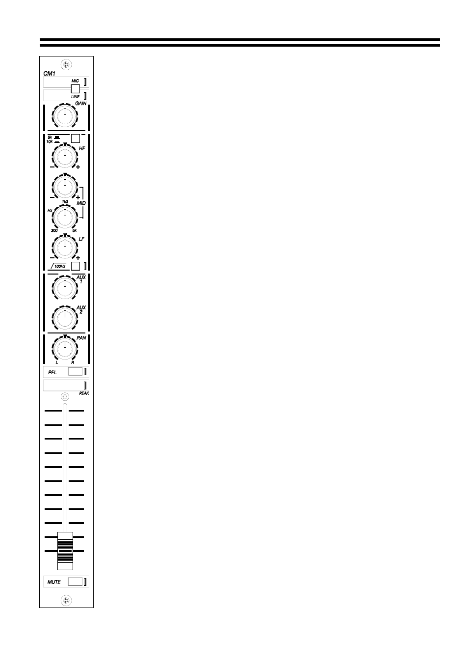
CM1 Microphone module
2.01
Input Select Switch
This two position switch is used to select the desired input source. The 'Mic' position,
indicated by a green LED is used for the microphone input. The 'Line' position,
indicated by a yellow LED is used for line level inputs such as high output capacitor
microphones or radio mics. The CM1 can have two inputs permanently connected,
using the input switch to select one or other inputs, it is however more common to
have one input per module.
2.02 Mute
Switch
This momentary action switch is used to conveniently turn the microphone channel on
and off. In normal use, the channel fader is left in the maximum position and the mute
switch is used to activate the channel, a red LED illuminates when the channel is
muted.
2.03 Channel
Fader
In general, the channel fader should be set to the maximum position. This position of
the fader is not critical but a situation where the fader is operated below 50% of its
travel should be avoided as this will degrade the normally excellent signal to noise
ratio.
The operator can activate the channel by the mute switch or sliding the fader from one
extreme to the other.
2.04 Gain
Control
With the mute switch in the 'On' position, the channel fader in the maximum position
and the master mic fader set to 75% of it's travel, the gain control can be adjusted to
give the required level.
2.05 Equalisation
The four equalisation controls (or EQ) and one switch will alter the tone of the audio
passing through the channel. It is not normal to assume that correct equalisation will
require all controls to be rotated off their centre detented position at the same time.
Note: if all three controls are rotated clockwise, then a previously optimised gain
setting, could still produce overload and distortion at the boosted high, middle and low
frequencies. If large amounts of EQ are needed to produce normal listen quality then
the user should be check the condition of input source (eg. damaged microphone,
microphone incorrectly wired) or even faulty audio wiring.
2.05a
HF- High Frequency
The HF control is used to adjust the treble content of the microphone signal, a centre
detent is provided, with clockwise movement to boost treble and anti-clockwise rotation
to reduce treble. An adjacent switch selects the operating frequency of 5KHz or
10KHz. With poor quality speakers the 10KHz setting might appear to have little effect.
2.05b
MID - Middle Frequency
The middle frequencies are controlled by two rotary controls, the upper control is used
to adjust the amount of boost or cut and has a centre detent for positive neutral
settings. The lower control selects the frequency of operation in the range 300Hz to
5KHz. Slightly reducing, or 'cutting' the EQ at frequencies around 600Hz to 1.2KHz will
give a rich sound to any microphone user.
30-08-02 V4.0