Cloud Electronics CXM2 User Manual
Page 8
CXM User manual
7
2.05c
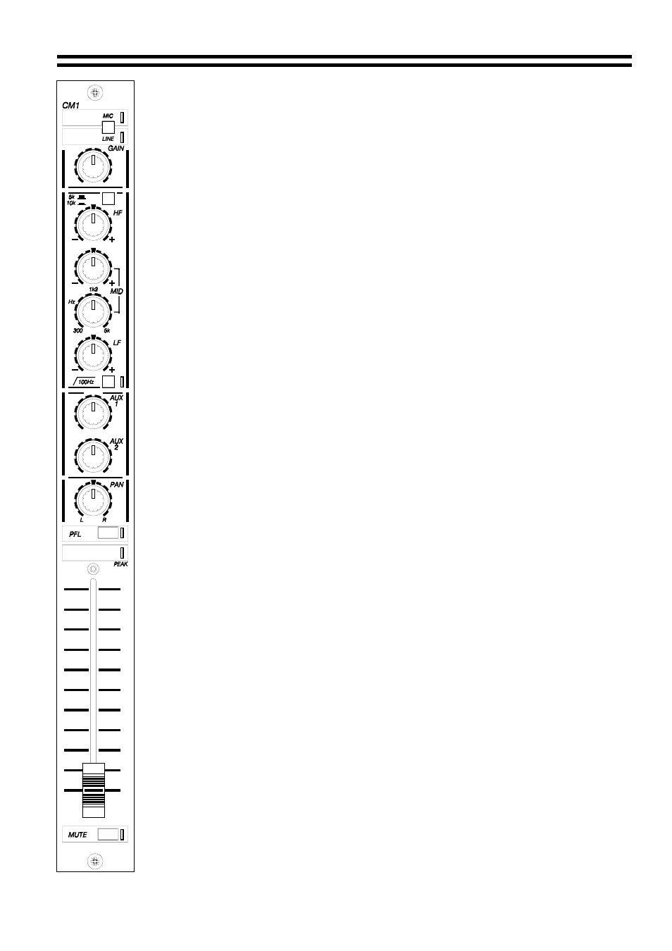
LF - Low Frequency
This adjusts the bass content of the audio signals, again with a centre detent and
similar operation to the HF control. Be careful not to add too much low frequency boost
as this will over emphasise any hard sounding consonants and microphone handling
noises. If a humming sound increases when the LF control is rotated clockwise then
the input device might be incorrectly wired.
2.05d
100 Hz High Pass Filter
This high pass filter operates at 100Hz and effectively reduces low frequency rumble
and other extraneous signals. It can be used to good effect to enhance vocal
projection, particularly when bass boost is used. The adjacent yellow LED illuminates
when the filter is operating. Do not be afraid to use this facility, as a human voice
produces very little sound below 100Hz.
2.06
PFL Select (Pre-fade listen)
This switch routes the pre-fade signal (not controlled by the fader) to the pfl display on
the master module and to the headphone amplifier. The switch will automatically
cancel previous selections and two or more channels can be selected simultaneously.
2.07 Peak
LED
This red LED is used to indicate that the channel is close to or has reached the
threshold of distortion. If the LED illuminates, the gain control must be reduced and set
in accordance with 2.04.
2.08
AUX 1 and AUX 2 - Auxiliary sends
The auxiliary send controls provide a useful, flexible output facility that can be used to
interface a variety of units for signal processing, such as sampling or digital delay
effects.
They can also be used as a flexible extra output facility. Unless configured differently
by the installation engineer, the factory settings for the Aux outputs are:-
Aux 1 is normally configured to operate with pre-fade signals (i.e. signals not controlled
by the fader).
Aux 2 is normally operated in the post fade mode (i.e. signals are controlled by the
fader).
2.09 Pan
The pan control will position the input source in the stereo image. The normal position
is centre detented.
One use of pan is where the CM1 channel was being used for a microphone user who
is 'on-the-move'. As the person approaches speakers on one of the stereo sides, (eg.
left), the pan control can be rotated towards the speaker on the other side (eg. right).
This would prevent feedback howl and still retain output level.
30-08-02 V4.0