Introduction - continued, Mounting - mechanical, Wiring – Cloud Electronics BE-1 User Manual
Page 2
BE-1 Installation Guide v1.0
2
Introduction - continued
The BE-1 will generally be installed in zones where such equipment is likely to be
required. It is also useful for connecting additional permanent equipment with balanced
outputs (the DCM-1 having only one rear panel balanced line input), in which case it
may be installed adjacent to the main equipment rack housing the DCM-1.
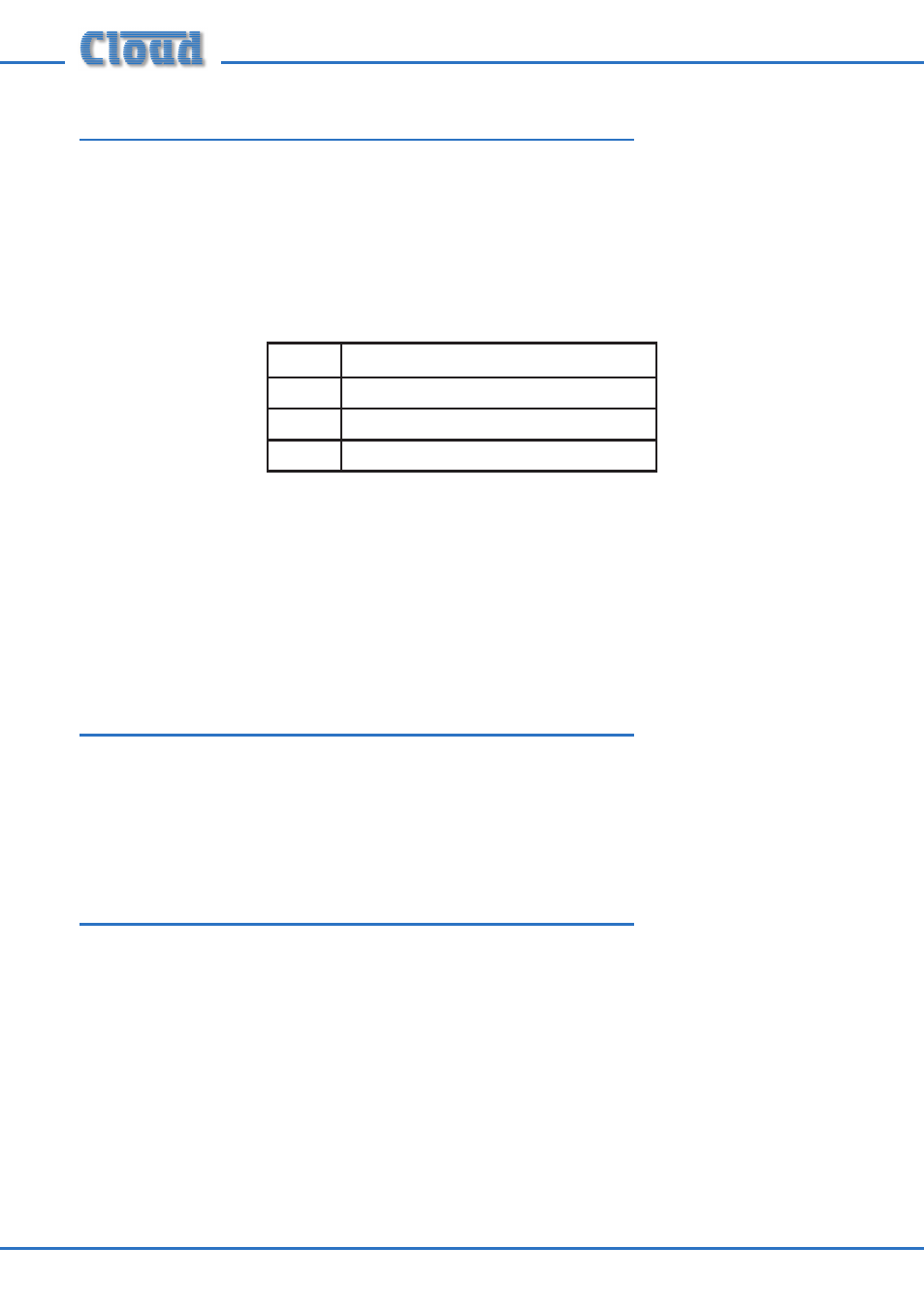
The input connectors are latching 3-pin female XLRs, wired to the industry-standard
pinout:
PIN
FUNCTION
1
Ground
2
Signal ‘hot’ (+, phase)
3
Signal ‘cold’ (-, antiphase)
The BE-1’s are electronically balanced, and are optimised for use with signals at a
nominal level of 0dBu. No gain adjustment is provided on the panel; if the signal level
from the connected equipment is too low or too high, it should be adjusted at source.
Note that the BE-1 does not provide electrical isolation and external transformers
should be employed if isolation is needed and the source equipment does not have
transformer-coupled outputs.
Mounting - mechanical
The Cloud BE-1 fits a standard dual-gang electrical back box. The back box used should
have a depth of at least 35mm (1.25”). Note that the BE-1 is made in various faceplate
sizes to suit standard electrical plate sizes in use in the UK, USA and Australia; ensure
you have the correct version for your territory.
Wiring
The BE-1’s OUTPUT connector should be connected to one of the DCM-1’s
EXTENSION PORTs (Line inputs 1 to 4) with screened CAT-5 cable and shielded
RJ45 plugs. Do not connect any other equipment to the phono sockets of the same-
numbered Line Input on the DCM-1.
Note that because the cables carry low-level audio, only screened CAT-5 should be
used, the foil screen of the cable being bonded to the metal screening can of the plugs.
If a BE-1 is being mounted in close proximity to the DCM-1, it may be possible to
use ready-made screened CAT-5 “patch” cables of an appropriate length. Otherwise,
shielded RJ45 plugs should be crimped onto the installed screened CAT-5 cable using
the pinout shown below.