Connecting multiple be-1s, Be-1 installation guide v1.0 3, Be-1 – Cloud Electronics BE-1 User Manual
Page 3
BE-1 Installation Guide v1.0
3
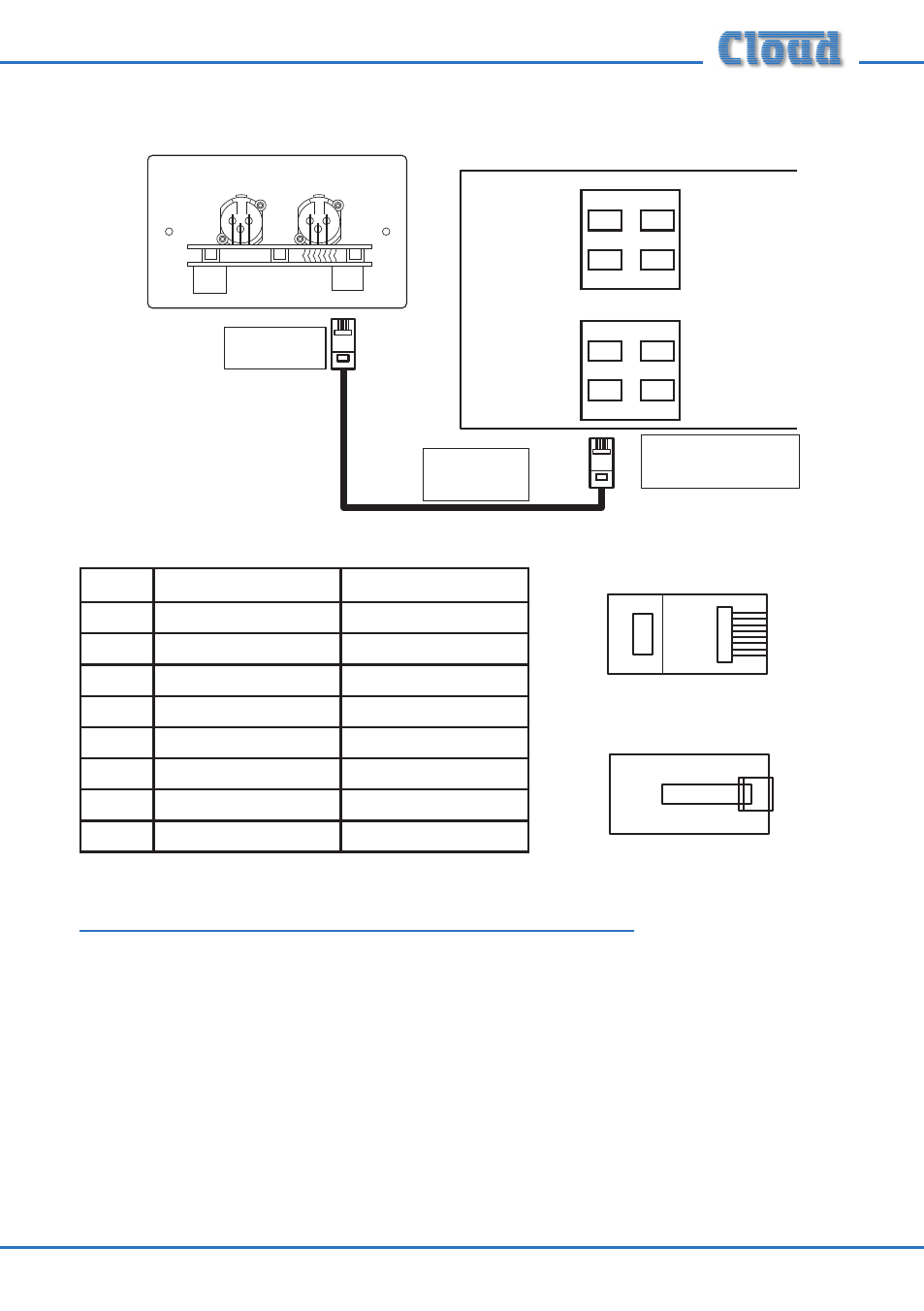
Connect to
Output socket
Screened
CAT-5 cable
Microphone Inputs
Extension Ports
DCM-1
1
2
3
4
1
2
3
4
Connect to an
unused Extension Port
LINK
OUTPUT
BE-1
PIN
USE
CAT-5 CORE
1
Left (cold)
White + Orange
2
Left (hot)
Orange
3
Sense
White + Green
4
DC +ve
Blue
5
0v
White + Blue
6
DC -ve
Green
7
Right (hot)
White + Brown
8
Right (cold)
Brown
Connecting Multiple BE-1s
Multiple BE-1s may be “daisy-chained” together to provide input points at different
locations in the same zone. Signals applied to plates wired in this way will be summed
together to the DCM-1 Line Input to which the “last” BE-1 in the chain is connected.
An internal gating circuit on each plate automatically “disconnects” any chained plates
which are not in use, to minimise noise contribution. Chained plates will be treated as
a single line input at the DCM-1.
Multiple BE-1s in the same zone may be daisy-chained by connecting the LINK RJ45
socket on the first BE-1 (that whose OUTPUT socket is connected directly to the
DCM-1) to the OUTPUT socket on the second BE-1, and so on, as shown on page 4.
1
8
1
8
1
8
1
8