Administrator guide – Code Blue IP1500 VOIP SPEAKERPHONE User Manual
Page 13
Code Blue
•
259 Hedcor Street
•
Holland, MI 49423 USA
•
800.205.7186
•
www.codeblue.com
GU-137-E
page 13 of 66
IP1500 and IP2500 Series
Administrator Guide
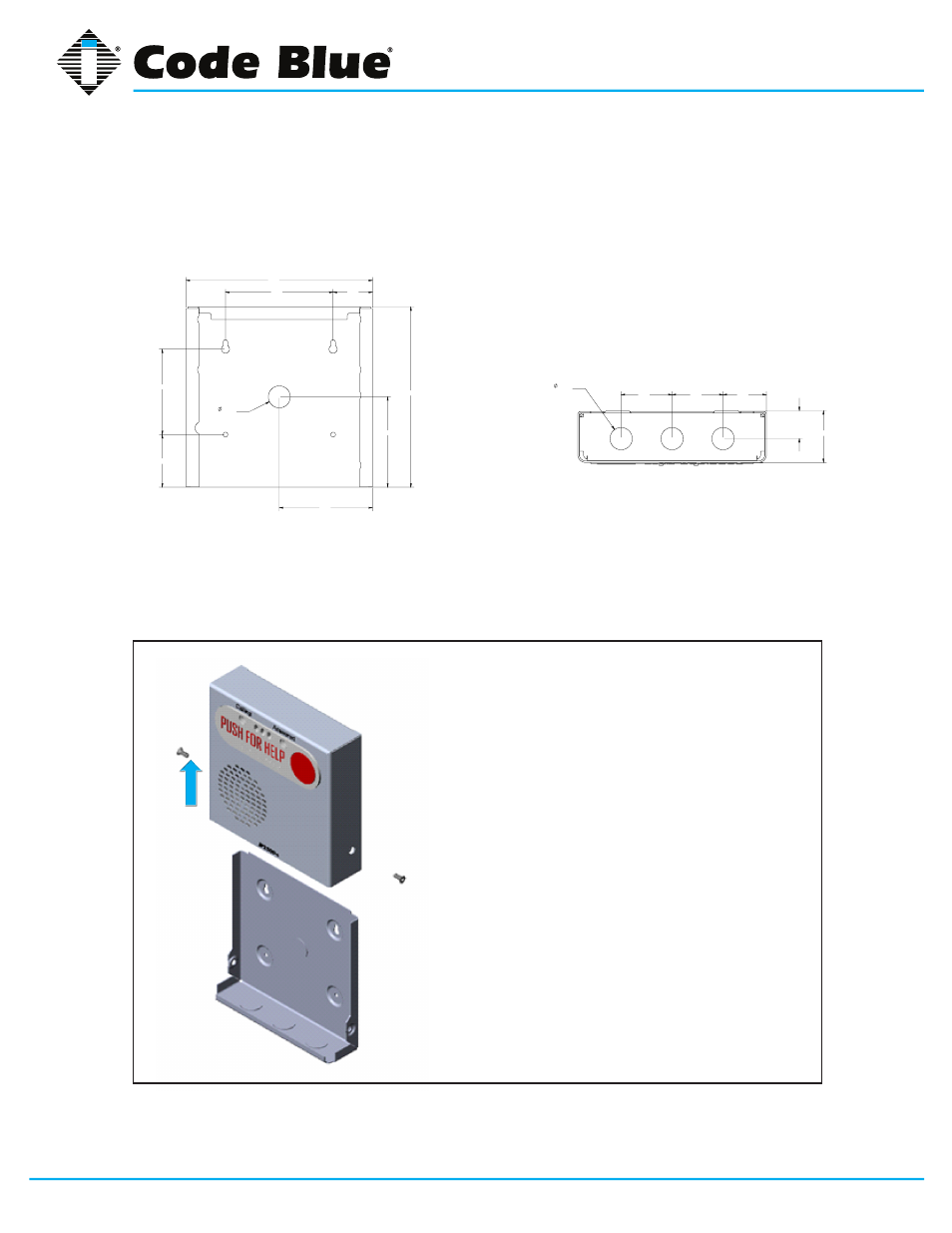
5.3 Surface Mount IP2500 Series
IP2500 Series Surface Mount: 7.25”w x 7.25”h x 2.00”d
7.41
7.17
3.59
3.70
1.56
4.28
2.09
3.39
.88
KNOCK OUT
1.70
2.00
2.00
1.10
.88
KNOCK OUT
2.03
7.41
7.17
3.59
3.70
1.56
4.28
2.09
3.39
.88
KNOCK OUT
1.70
2.00
2.00
1.10
.88
KNOCK OUT
2.03
Back View
• First, remove the two retaining screws, one from
each side of the case
• Remove the rear mounting plate by sliding it
downward
• Use the mounting plate as your guide on the
wall, mark the mounting and conduit holes
• Remove the rear mounting plate and create the
required holes, attach the mounting plate to the
wall
• Pull CAT 5e cable through the conduit hole in
the rear mounting plate
• Connect CAT 5e cable to the Ethernet port on
the PCB
• Slide the IP2500 Series case down, starting
from the top of the rear mounting plate
• Replace the two retaining screws
Bottom View
Vertical
Orientation
NOTE: By design, no main gasket is needed to seal the enclosures. The installer is responsible for
sealing all screws with thread seal, as well as applying the proper conduit for a weather-tight seal.