2 out female bnc connector (j16) -11, 3 balanced 15-pin female ‘d’ sub connector -11, 4 clk out (j17) -11 – Comtech EF Data MM200 User Manual
Page 87: 5 clk in female bnc connector (j18) -11, 15 parallel rs-422/dvb, m2p -11
MM200 High-Speed Microwave Modem
Electrical Interfaces
TM086 - Rev. 4.1
5-11
5.14.2 OUT Female BNC Connector (J16)
Provides E1 Data Output from the receiver.
5.14.3 BALANCED 15-pin female ‘D’ sub connector
Provides T1 Data Input and Output at the following pinouts:
Table 5-8. Balanced 15 Pin Female ‘D’ Sub Connector
Pin No.
Signal
Direction
1
SD-A
In To Modem
9
SD-B
In to Modem
3
RD-A
Out From Modem
11
RD-B
Out From Modem
2,4
GND
Ground
5.14.4 CLK OUT (J17)
Not Used
5.14.5 CLK IN Female BNC Connector (J18)
Accepts the Reference Clock Input.
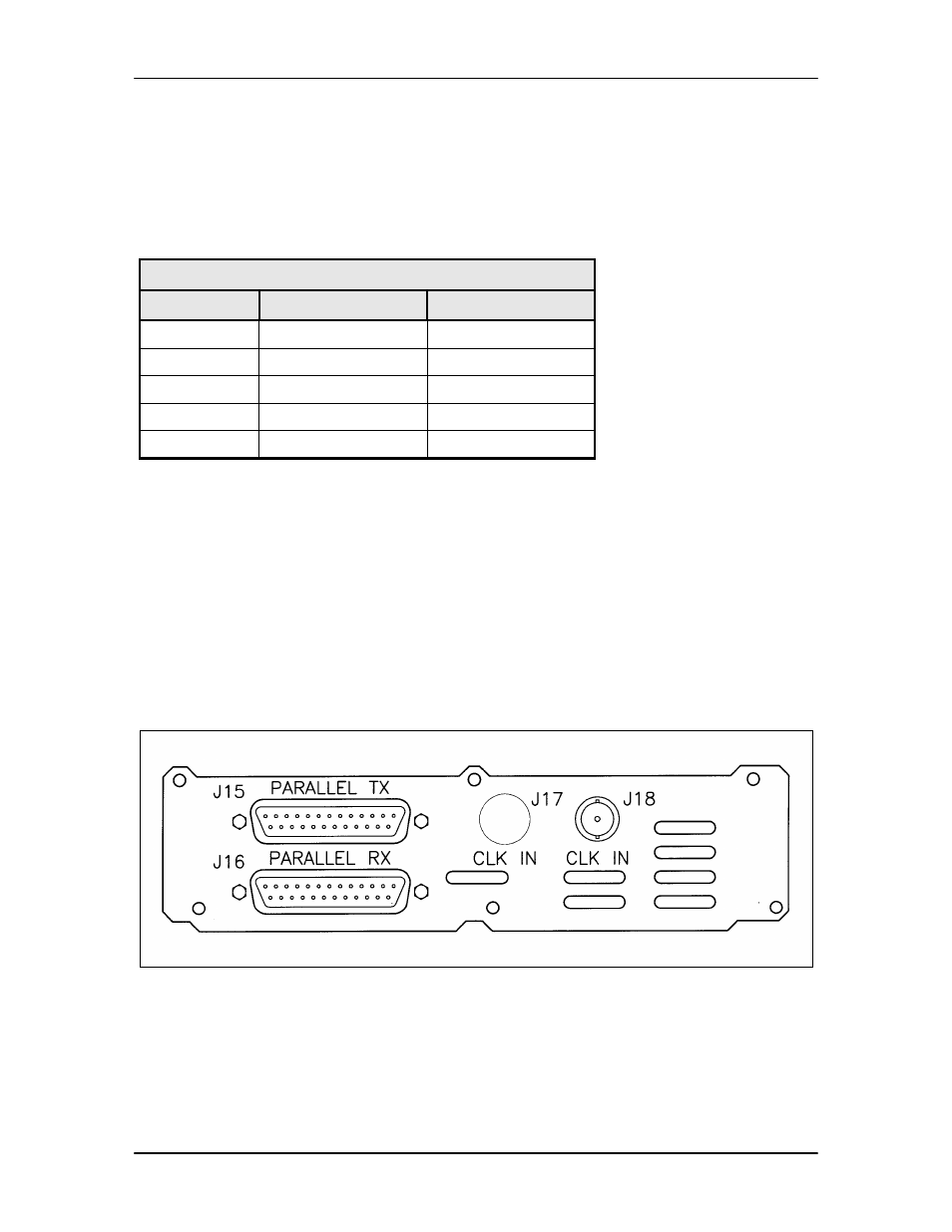
5.15 Parallel RS-422/DVB, M2P
This rear panel interface (Figure 5-8) provides DVB or M2P via a Front Panel selection. It can be
ordered with RS-422 or LVDS Levels.
Figure 5-8. Parallel RS-422/DVB, M2P and Parallel LVDS/DVB, M2P