Comtech EF Data LCS-4 User Manual
Page 37
LCS-4 L-Band Combiner Switch
Revision 1
Low Noise Block Assembly
MN/LCS4.IOM
1. Remove all protective tape from switch
and keep it clean.
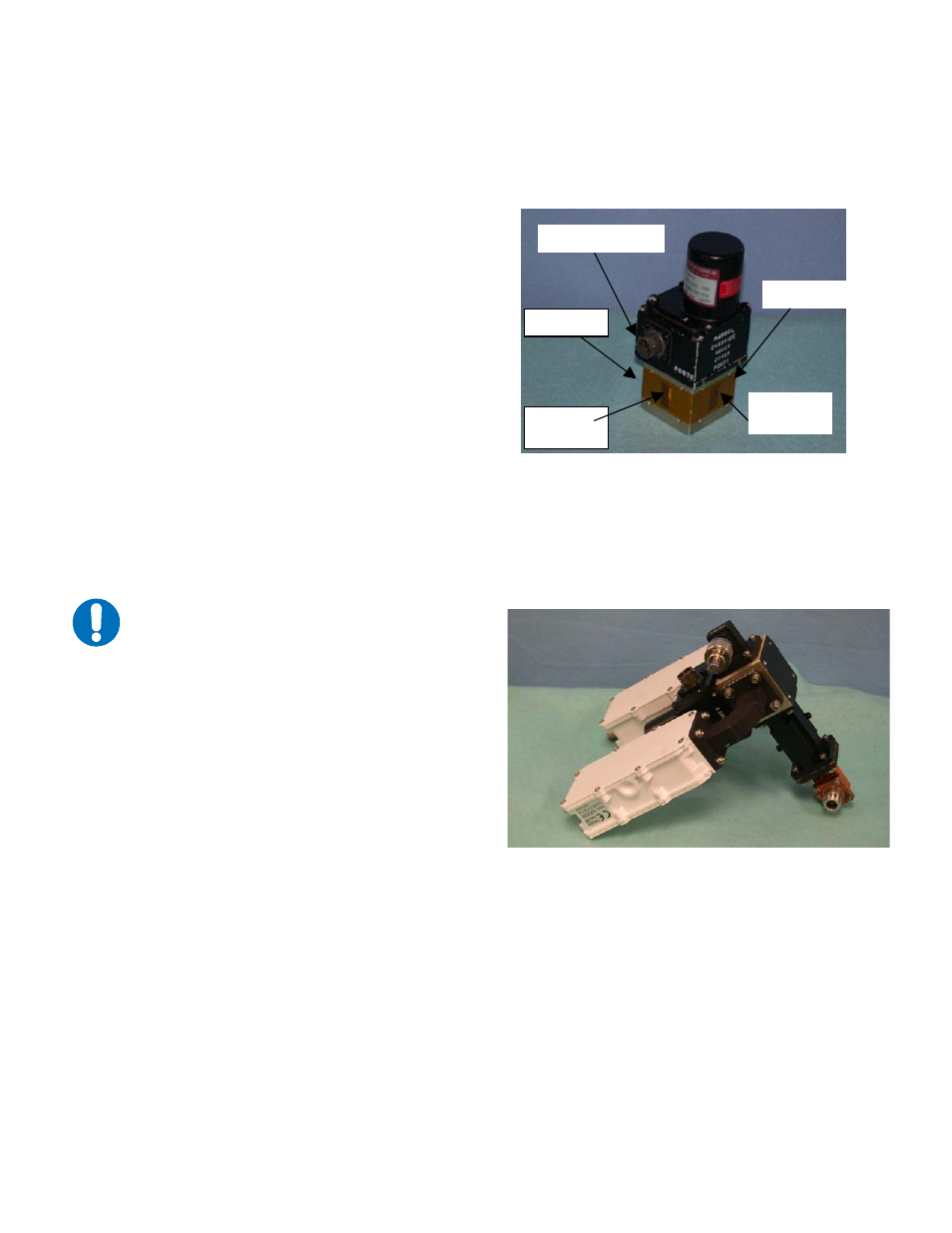
Figure 4-5. Switch Port Locations
2. Position LNBs and gaskets
(GA/GSKTCP75HALF) on Port 2 and
Port 4 of switch.
3. Secure each LNB with eight bolts,
flat washers, and split washers.
4. Position adapter (RF/ADP-WR75-N)
and gasket on Port 3 and secure with bolts,
flat washers, and split washers.
5. Place termination (CN/CX50NMALE)
on threaded port of adapter.
6. Position the customer-furnished TRF filter
and a gasket on Port 4 of the switch.
7. Install the optional support bracket
(FP/BR0085). Secure with eight bolts,
flat washers, and split washers.
8. Set assembly aside for later installation.
IMPORTANT
Ensure that the OUTPUT flange of the filter
is against the switch.
Figure 4-6. Ku-Band LNB Switch
Port 1
Port 2
Port 3
Connector
Port 4
4–9