Comtech EF Data RCF6001 User Manual
Page 18
Installation
RCF6001 Satellite Terminal
Page 2-6
TM082 - Rev. 1.0
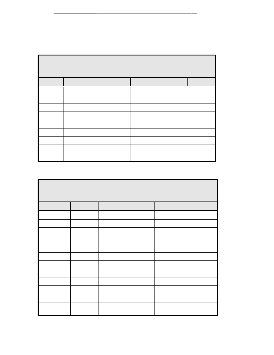
J4 - Remote
The RS-485 connection is for remote monitor and control of the modem.
Refer to Table 2-4 below for the pinouts.
Table 2-4.
J4- RS485 Remote Port - 9-Pin Female ‘D’
Pin No.
Signal
Description
Direction
1
RS485 TxD-B
Transmit Data B
Output
2
TxC-A
Transmit Clock A
Output
3
TxC-B
Transmit Clock B
Output
4
RxC-A
Receive Clock A
Input
5
Common
Signal Common
6
RS485 TxD-A
Transmit Data A
Output
7
RxC-B
Receive Clock B
Input
8
RS485 RxD-B
Receive Data B
Input
9
RS485 RxD-A
Receive Data A
Input
J9 – Data Interface
Table 2–5.
J9 - Sync Data RS422/RS485/RS232/V.35 - 37-Pin Female
Pin Number
Signal
Description
Direction
4
SD-A
Send Data A (-)
Input
22
SD-B
Send Data B (+)
Input
5
ST-A
Send Timing A (-)
Output
23
ST-B
Send Timing B (+)
Output
6
RD-A
Receive Data A (-)
Output
24
RD-B
Receive Data B (+)
Output
7
RS-A
Request to Send A (-)
Input
25
RS-B
Request to Send B (+)
Input
8
RT-A
Receive Timing A (-)
Output
26
RT-B
Receive Timing B (+)
Output
9
CS-A
Clear to Send A (-)
Output
14
MF
Mod Fault - Open
Collector
Output