Major assembly, Installation – Comtech EF Data CMR-5940 Quick Start Guide User Manual
Page 2
Major Assembly
The Comtech EF Data CMR-5940 Digicast PID Filter RS-422 is available in a standalone configuration. The
following table lists the components provided with a standard configuration. In the event any listed item is
missing, please contact Comtech EF Data Customer Support.
CMR-5940 Digicast PID Filter RS-422 – Standalone Configuration
Quantity Description
1
CMR-5940 Digicast PID Filter RS-422
1
SPU24-102 Power Supply
1 IEC
Power
Cable
1
CA-TERMINAL Terminal Cable
1
CD (includes Quick Start reference and Installation and Operation Manual)
1
Quick Start sheet
Installation
The CMR-5940 is designed for ease of installation and configuration. Once the unit has been removed from the
packing container, follow these instructions:
Step
Procedure
1
Place the CMR-5940 on a flat surface with free-air flow where the LEDs can be clearly observed with
unrestricted access to the rear panel of the unit.
2
Connect the DC power connection to the connection labeled PWR on the back of the unit and tighten the
restraining nut to ensure secure operation.
3
Connect an RJ-45 Ethernet cable (patch cord) to the port labeled ETHERNET. This cable should be connected
to an Ethernet concentrator (hub) or switch.
4
Connect a terminal cable (supplied) to the port labeled TERM. This cable should be connected to a PC’s serial
port (DB-9) to initially configure the CMR-5940.
5
Connect the AC power cord between a standard wall outlet and the power supply. The blue LED will illuminate.
6
IMPORTANT
It is recommend that the ASI and RS-422 cables NOT be connected until the unit has been
completely configured.
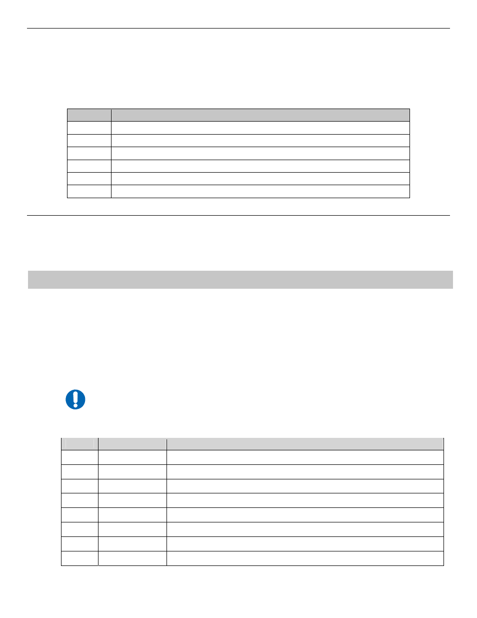
7
Upon startup, the LEDs on the CMR-5940 front panel become operational as follows:
LED
Function Label
Description
Blue
PWR
LED illuminates if power is properly applied
Red
ALARM
LED may illuminate since the unit is not yet configured
Green
SYNC
LED illuminates if the ASI in SYNC is detected
Green
RED
LED will not illuminate – reserved for future redundancy functionality
Amber
E-COL
LED flashes if there are collisions on the Ethernet switch
Green
E-RX
LED flashes if there is activity on the switch
Green
E-TX
LED flashes if the unit is transmitting data to the Ethernet
Green
E-LINK
LED illuminates if the Ethernet connection to the Hub/Switch is operational
Copyright © 2007 Comtech EF Data, 2114 West 7th Street, Tempe, Arizona 85281 USA. All rights reserved. Printed in the USA.