Crs-120 optional mounting panel, 1 crs-120 optional mounting panel – Comtech EF Data CRS-120 User Manual
Page 24
1:1 Redundancy Switch
Revision 3
Installation
MN/CRS120.IOM
2–2
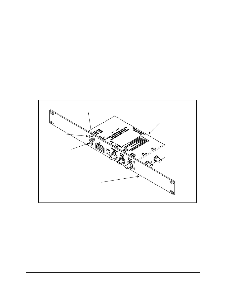
2.2.1 CRS-120 Optional Mounting Panel
An optional mounting panel (KT/11084-2) is available to attach the 1:1 redundancy switch to the
standard 19-inch cabinet. Install Mounting Panel as follows:
1. Remove two bottom switch screws (Figure 2-1)and set a side.
2. Remove two upper switch screws and discard.
3. Remove grounding nuts and washers from grounding lug and set aside.
4. Position mounting panel onto switch.
5. Reinstall gounding nuts and washers previously removed.
6. Reinstall two bottom switch screws previously removed.
7. Install two kit screws (component of KT/11084-2) and secure.
CRS-120 Switch
Optional: Mounting Panel
Grounding Lug Nuts and
Washers
Switch Screw
(Typical 2 Places)
Kit Screw
(Typical 2 Places)
Figure 2-1. CRS-120 Optional Mounting Panel