Comtech EF Data SMS-458B User Manual
Page 99
SMS-458B Modem Protection Switch
Revision 2
Cable Configuration
MN/SMS458B.IOM
A–3
A.2
SDM-2020 Modulator (TX only) with G.703 Data Interface
Perform the following installation procedures.
1. Install SMS-458B Modem Protection Switch in a rack. Secure the switch in
place.
2. Ensure cable assemblies are available for installation, refer to Figure A-1
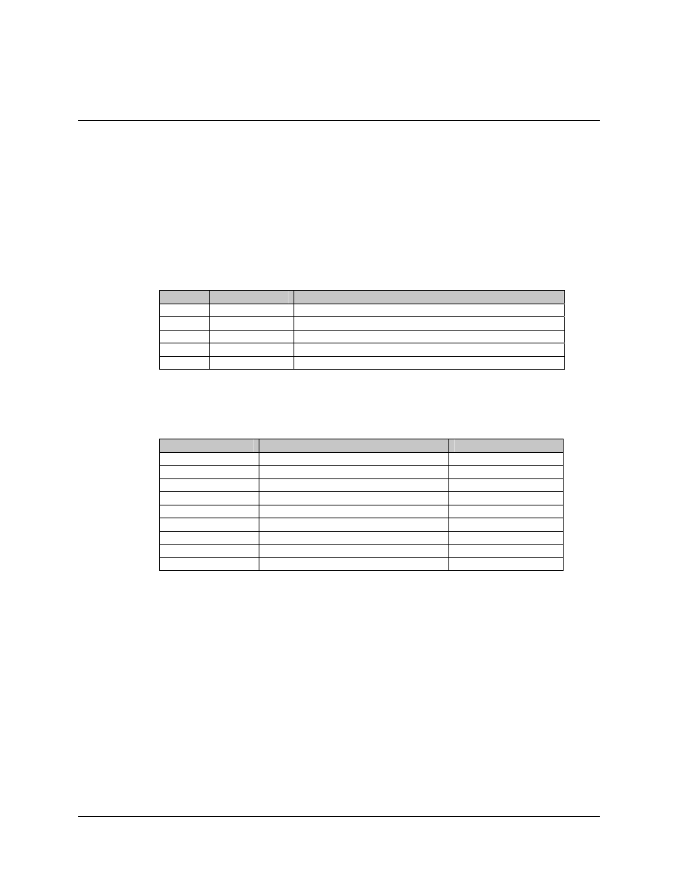
Table A-2. Cable Assembly
QTY
Part No.
Nomenclature
1
CA/0755
Cable Assy, Control
5
CA/0813-4
Cable Assy, BNC
1
CA/0953
Ground Cable, Strap
5
CA/7706-1
Cable Assy, Interface (50-to-9-Pin)
2
WI/17250
Power Cord
3. Connect cable assemblies are specified in Table A-3.
Table A-3. Cable Connection
Cable Part No.
SMS-458B
SDM-2020M
CA/0755
Modem Control J3
Remote J1
CA/0813-4
Prime Mod Inputs J18 through J21
CP1 TX-IF
CA/0813-4
Backup Mod Input J26
CP1 TX-IF
CA/0953 Ground
J39
CA/7706-1
Prime Modem J6
J5 AUX
CA/7705-1
Backup Modem J3
J5 AUX
WI/17250
Power Input J27 and J38
CA/0813-4
Prime TX Data
G.703 DATA OUT J4
CA/0813-4
Backup TX Data
G.703 DATA OUT J4