Comtech EF Data DD2401 User Manual
Page 69
DD2401 Satellite Demodulator
Electrical Interfaces
MN-DD2401 - Rev. G
5-
1
Electrical Interfaces
5
5.0 DD2401 Connections
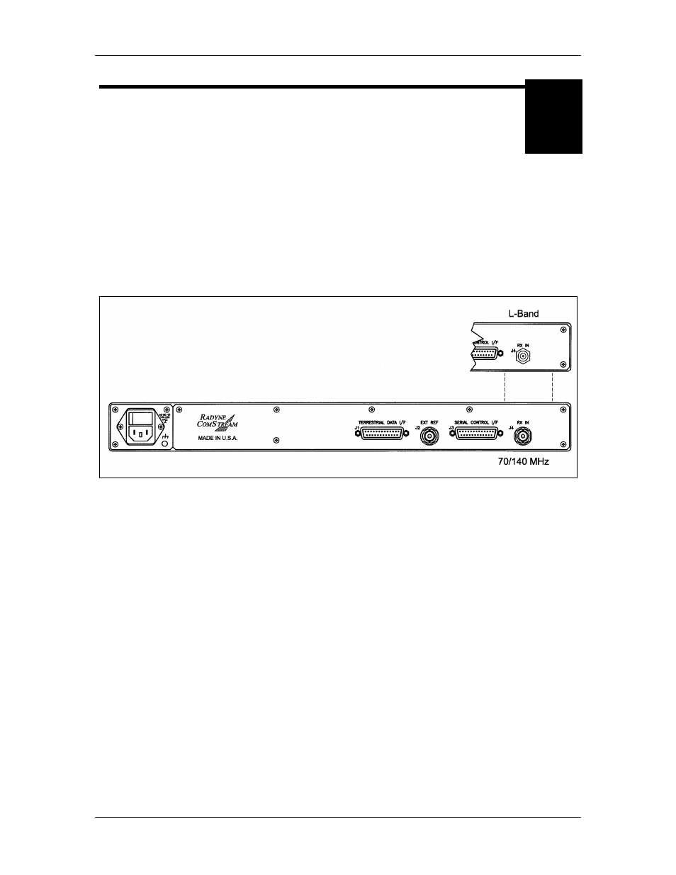
All DD2401 connections are made to labeled connectors, and to any optional interfaces installed
in slots located on the rear of the unit. Any connection interfacing to the DD2401 must be the
appropriate mating connector. Refer to Figure 5-1 for connector locations.
Note: Shielded cables with the shield terminated to conductive backshells are required in
order to meet EMC Directives. Cables with insulation flammability ratings of 94 VO or
better are required in order to meet Low Voltage Directives.
Figure 5-1. DD2401 Satellite Demodulator Rear Panel Connectors
5.1 Power
The unit is powered from a 100 – 240 VAC, 50 – 60 Hz, 1A source. The switch located on the left
hand side (as viewed from the rear of the unit) turns power on and off to the unit. A chassis
ground connection can be made at the #10-32 threaded stud located to the lower right of the AC
Power Connector.