Comtech EF Data RCU108 User Manual
Page 21
RCU108 1:8 Protection Switch
Installation
TM066 - Rev. 1
Page 2-11
6
DSR----to pin 4
DSR ---to pin 4
2
7
RTS----to Pin 8
RTS----to Pin 8
4
8
CTS----to pin 7
CTS----to pin 7
6
9
N/C
TXData\
8
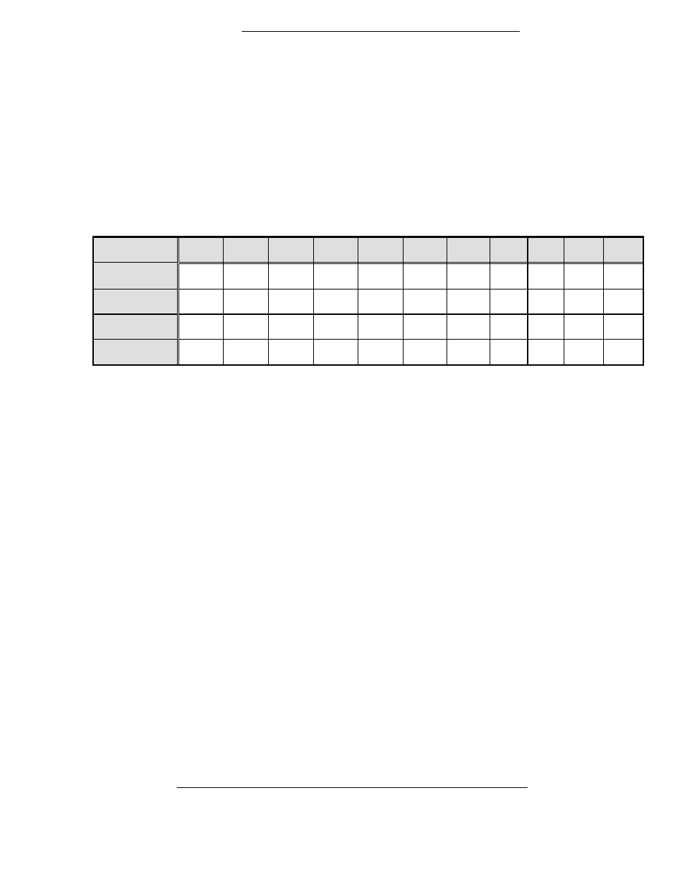
NOTE: In order to obtain these signals at the output connector, the jumper configuration on the
AS/3048 Controller PWB must have been performed as outlined in Appendix B. A summary of
jumper selections is as follows:
Configuration
JP4-1
JP4-2
JP4-3
JP4-4
JP4-5
JP4-6
JP3
JP5
JP6
JP7
JP8
RS232
OUT
OUT
OUT
OUT
IN
IN
OUT
OUT
IN
OUT
OUT
RS422
IN
IN
IN
IN
OUT
OUT
OUT*
OUT
OUT
OUT
IN
RS485
IN
IN
IN
IN
OUT
OUT
OUT*
OUT
OUT
OUT
IN
485 1/2 DPLX
IN
OUT
OUT
IN
OUT
OUT
OUT*
IN
OUT
IN
IN
* Receiver terminations for twisted pair RS422/485 can be optionally terminated at 120 ohms by
installing JP3. Factory-supplied cables for multiple converter "daisy chain" operation are
terminated at the cable ends.