2 mounting, 3 lnb connector pinouts – Comtech EF Data LNB User Manual
Page 16
LNB Low Noise Block Downconverter
Revision 0
Installation
MN-LNB
2–2
2.2
Mounting
No special tools are required.
Waveguide flange contains 8-32 threaded holes for single unit configuration or #8 screw thru-
holes for optional redundant configurations.
2.3
LNB Connector Pinouts
LNB can be supplied with the following connector configurations, depending on the
model and options:
• 4 pin
• 6 pin
See Table 2-1 below
CAUTION
Use of Power Supply Voltage greater than +24Vdc may cause damage
to the LNB.
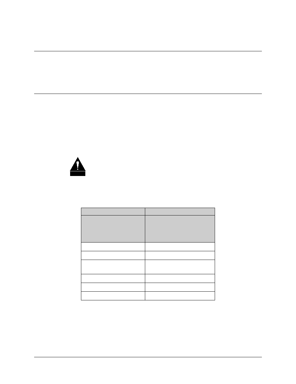
Table 2-1. LNB Connector Pinouts
4-Pin
6-Pin
ITT Cannon KPT02A8-4P
Mating Conn. (Female):
Amphenol: PT06E84S
ITT Cannon MS3112E10-6P
Mating Conn. (Female):
Amphenol MS3116F10-6S
A: +12 to +24VDC Input
A: +12 to +24VDC Input
B: GND
B: GND
C: FLT - NO (NC or open
collector optional)
C: GND
D: Fault common
D: FLT – NO
E: FLT – Common
F: FLT – NC
Normally Open or Closed contact refers to faulted condition