3 phase rhp - hybrid solid state contactors – Crydom RHP Series User Manual
Page 2
3 Phase RHP - Hybrid Solid State Contactors
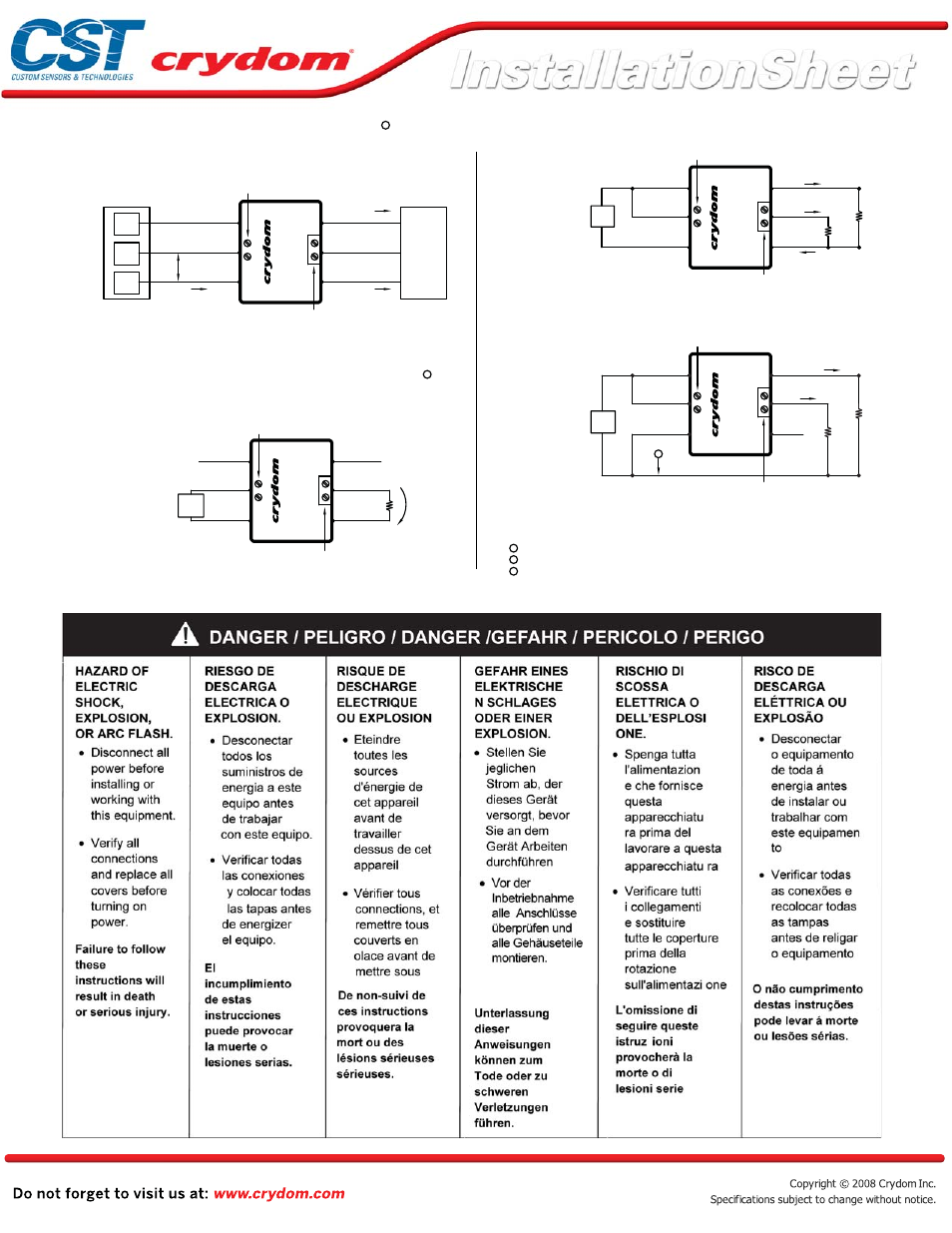
Typical Electrical Connection for 3 Phase Applications
Optional Electrical Connections for Single Phase Applications
~
HYBRID SOLID STATE
CONTACTOR
120/240 VAC
Single Phase
Operating Voltage
I L1
R1
1L1
3L2
5L3=NC
IL1 ≤ Rated current
6T3=NC
Line
Neutral
DC Input/Control Voltage
(D5, D12, D24 input versions)
-
+
~
HYBRID SOLID STATE
CONTACTOR
120/240 VAC
Single Phase
Operating Voltage
IL2 ≤ Rated current
IL3 ≤ Rated current
IL2 + IL3 > Rated current
I L3
I L2
R1
R2
NC
Line
Neutral
1L1
3L2
5L3
DC Input/Control Voltage
(D5, D12, D24 input versions)
-
+
~
HYBRID SOLID STATE
CONTACTOR
-
+
120/240 VAC
Single Phase
Operating Voltage
IL1 = (IL2 + IL3) ≤ Rated current
I L3
I L1
I L2
R1
R2
1L1
3L2
5L3
DC Input/Control Voltage
(D5, D12, D24 input versions)
Line
Neutral
HYBRID SOLID STATE
CONTACTOR
~~~
-
+
VLL
I L1
I L3
DC Input/Control Voltage
(D5, D12, D24 input versions)
3Ø
Load
I L1
5L3
3L2
1L1
6T3
4T2
2T1
3 Phase AC
Operating Voltage
AC Input/Control Voltage
(E, F, G input versions)
AC Input/Control Voltage
(E, F, G input versions)
AC Input/Control Voltage
(E, F, G input versions)
AC Input/Control Voltage
(E, F, G input versions)
The single phase supply voltage must be wired to terminal 1L1 and 3L2 for proper single phase operation.
In applications switching two single phase loads (R1 and R2) where the combined load current exceeds
the contactor’s rating (40 or 50 Amps) the return/neutral lead must not be wired through the contactor
(see above drawing).
6
Match VLL to voltage suffixes 28 & 60 for options E, F & G and 12 & 24 for options DX.
5
5
7
7
6
(For output voltage options 24, 28, 60)
(For output voltage options 12, 24, 28, 60)
DO NOT apply any AC voltage to contactor coil connections, for DC versions only.