Signal termination between displays, Primary - mirror, Figure 3 – Daktronics Fiber Optic Communication User Manual
Page 7
5. For displays with an internal fiber optic board only: Route the fiber cable into
the back of the display, being careful not to damage any interior components. Make
the connections to the fiber optic board as normal.
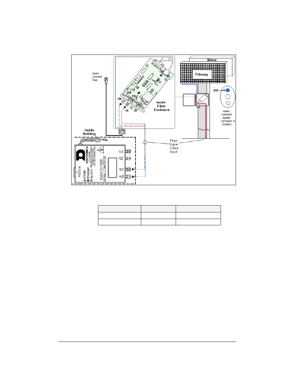
Figure 3: Signal Converter to Fiber Optic Enclosure
Signal Converter to Display Fiber Optic Board
Signal Converter Field Cabling
Fiber Optic Board
J2 Transmit (TX1)
(Color varies)
J5 Receive (RX2)
J3 Receive (RX1)
(Color varies)
J4 Transmit (TX2)
Signal Termination Between Displays
Reference Drawings:
Controller II, Galaxy, 8-conn, J1087 ......................................... Drawing B-204771
Primary - Mirror
Most displays are shipped as either a single Primary display or two displays in a 2V,
Primary – Mirror configuration.
The Primary – Mirror (2V) quick connect cable (W-1503) is used to terminate signal
between two displays. The six-foot cable goes from the Signal OUT (J34) on the
primary display to the Signal IN (J32) on the mirror display.
Fiber Optic Communication Manual
3