3 schematics, 4 led drivers – Daktronics DF-1020 User Manual
Page 32
Maintenance and
Troubleshooting
4-4
3. Disconnect all connectors from the driver. Release each connector by
squeezing together the locking tabs as you pull the connector free. Note:
When reconnecting, remember that these are keyed connectors and
will attach in one way only. Do not attempt to force the connections.
4. Remove the screws, nuts, or wing nuts securing the driver to the inside of
the enclosure.
5. Carefully lift the driver from the display and place it on a clean, flat surface.
6. Follow steps 1 through 5 in reverse order to attach a new driver.
4.3 Schematics
Reference Drawings:
Schematic; Multipurpose 4 Col. LED Drvr................... Drawing A-165028
Schematic; Gen III Outdoor LED, 8 Column Drvr ....... Drawing A-177935
Schematic; 16 Col Multipurpose LED Drvr.................. Drawing A-179599
Drawings A-165028, A-177935, and A-179599 are the schematic diagrams for the
4-, 8- and 16-column drivers used in the DataMaster Gas Price displays. The
schematics include power and signal inputs and all wiring for the models described
in this manual.
4.4 LED
Drivers
Reference Drawings:
4 Column MASC LED Driver Specifications ......... Drawing A-166216
8 Column MASC Driver Specifications ................. Drawing A-167237
16 Col. MASC Driver Specification ....................... Drawing A-184475
In the display, the LED drivers perform the task of switching digits on and off. Refer
to Drawings A-166216 or A-184475 for a complete listing of driver connector
functions and wiring pin numbers.
DataMaster Gas Price displays may use 4-, 8-, or 16-column drivers, depending on
the model and size of digits. Each 16-column driver has 20 or more connectors
providing power and signal inputs to the circuit, and outputs to the digits and
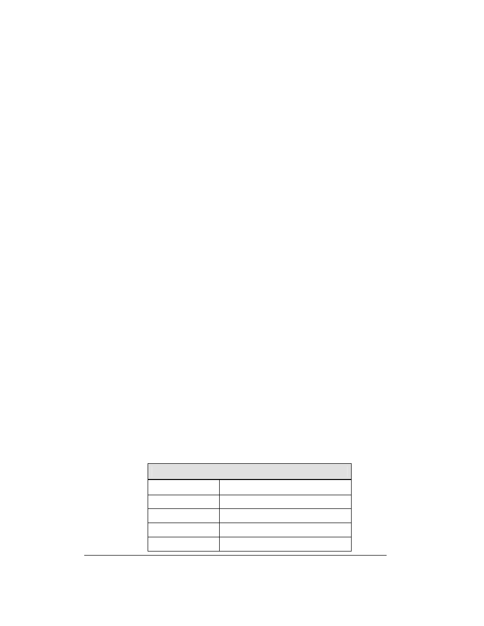
indicators. The following table describes connector functions for a 16-column driver.
(Major functions are the same on 4- and 8-column drivers.)
16-Column LED Driver
Connector No.
Function
J1 – 16
Outputs to digits
J17
Power and signal input
J18 Relay
J19 Address