Fiber optic, Fiber optic -13, Figure 26: modem phone line termination enclosure – Daktronics AF-3112-34-R,A User Manual
Page 33: Figure 27: fiber display layout, Figure 26
Advertising
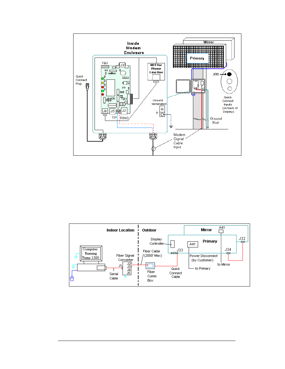
Figure 26: Modem Phone Line Termination Enclosure
Fiber Optic
Reference Drawings:
System Riser Diagram Fiber Comm. Box Term .......... Drawing A-187293
When fiber optic cable is used, a signal converter (0A-1127-0239), connected to the
computer, relays signal via fiber signal cable to the fiberboard (J4/J5) in the weather
resistant enclosure at the display. When connecting fiber cables, always connect
transmit to receive and receive to transmit. Refer to Drawing A-187293and
Figure 27: Fiber Display Layout
Note: The cable from the enclosure to the display can be routed though conduit, or
should be secured to prevent being pulled loose from the display by weather or
vandalism.
Electrical Installation
3-13
Advertising