Fiber optic, Fiber optic -12, Figure 29: modem/ signal – Daktronics AF-3180-64-R,A User Manual
Page 32: Figure 30: fiber display controller
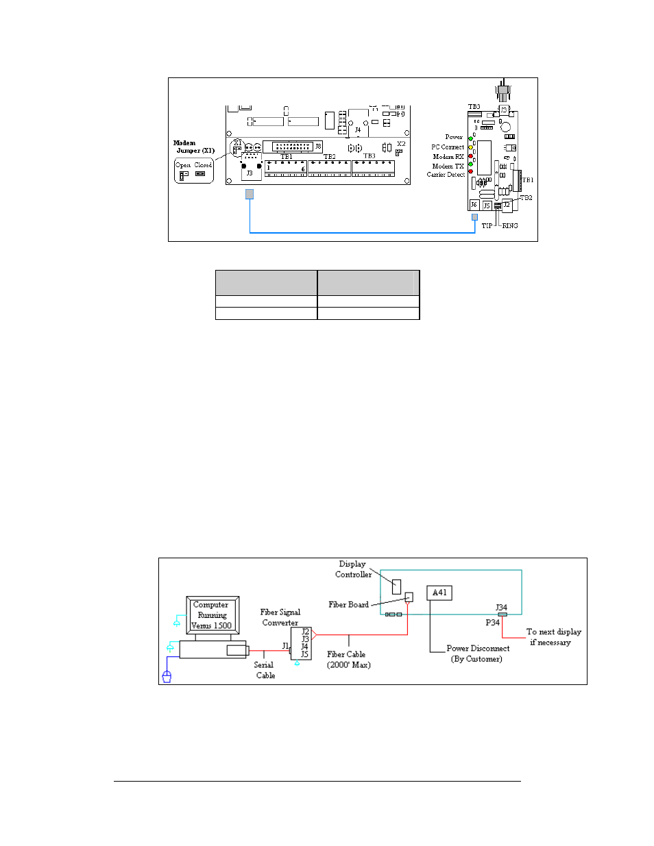
Figure 29: Modem/ Signal
Field Cabling
Phone Line
(A3x-TB2)
Red
Pin 1 (TIP)
Green
Pin 2 (RING)
Fiber Optic
Reference Drawings:
System Riser Diagram, Fiber ...................................... Drawing A-174344
Schem, Sig Wiring, Internal, W/QC PCB..................... Drawing B-177662
When fiber optic cables are used, signal from the converter enters the display and
connects to the fiberboard. Signal is then transferred from the fiberboard to the
controller.
1. Terminate the fiber from the signal converter to the fiberboard in the
display. Connect from J2 (TX) on the signal converter to J5 (RX) in the
display and from J3 (RX) on the signal converter to J4 (TX) in the display.
2. A straight-through 6-conductor phone cable with RJ11 connectors
(Daktronics part number 0A-1137-0160) relays the signal from J7 on the
fiber board to J3 (RS232 IN) on the controller. Refer to Drawing A-174344
for the system riser and to B-177662 for terminal block cabling.
Figure 30: Fiber Display Controller
Electrical Installation
3-12