5 fiber ethernet communication – Daktronics AF-3700-34 RGB User Manual
Page 28
Signal Installation
22
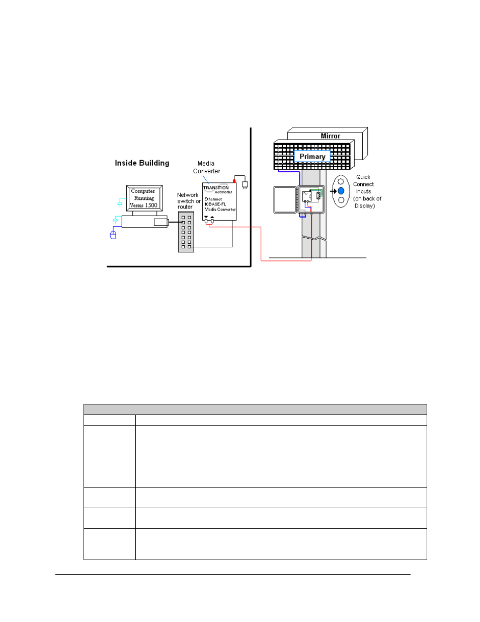
4.5 Fiber Ethernet Communication
If the communication system is Fiber Ethernet, look for:
• an indoor media converter connected to the network and to fiber cable.
• a second media converter outdoors located in an enclosure at the display.
Connections
• Computer to network − RJ45 cable from computer port into network switch.
• Network to first media converter − RJ45 cable from network switch/router into
media converter.
• Media converter’s 9-volt power adapter plugged into 120 VAC outlet.
• Indoor media converter to outdoor media converter − two fiber-optic cables run from
indoor media converter to second converter in the enclosure at display.
• Enclosure to display − quick-connect cable to the middle jack on display back.
DO NOT SHARPLY BEND fiber-optic cable at any point along the fiber cable.
Troubleshooting
Component Check:
Cable
Connections
•
The cable is connected from the computer to the network switch/router.
•
The network cable connects from network
switch
to media converter in building.
•
The indoor media converter power adapter is plugged in.
•
The fiber cables connect from the first media converter to the second one at display.
The “out” arrow on one will connect to an “in” arrow on the other.
•
The cable is connected from the enclosure to middle jack on display back.
Diagnostic
LEDs
•
Each media converter has a green power LED on, indicating power.
•
When the media converter transmits data, the “link” is ON and RX LEDs flash.
Display
Power
•
The display is either running a message or showing a single pixel flashing in the
bottom right corner of the display when power is on.
Software
•
The software is configured for TCP/IP communication.
•
The software and the display are set for the same network address.
•
Refer to the software manual for other possible conditions.
Figure 33: Fiber Ethernet Communication Layout