2 mlc diagnostics – Daktronics AF-3700-34 RGB User Manual
Page 36
Diagnostics and Troubleshooting
30
Figure 42 illustrates a GalaxyPro controller. Red diagnostic LEDs are located at various
places on the controller. The following table details some essential LEDs to monitor and the
information that each LED provides. The LED name and number are noted in Figure 42.
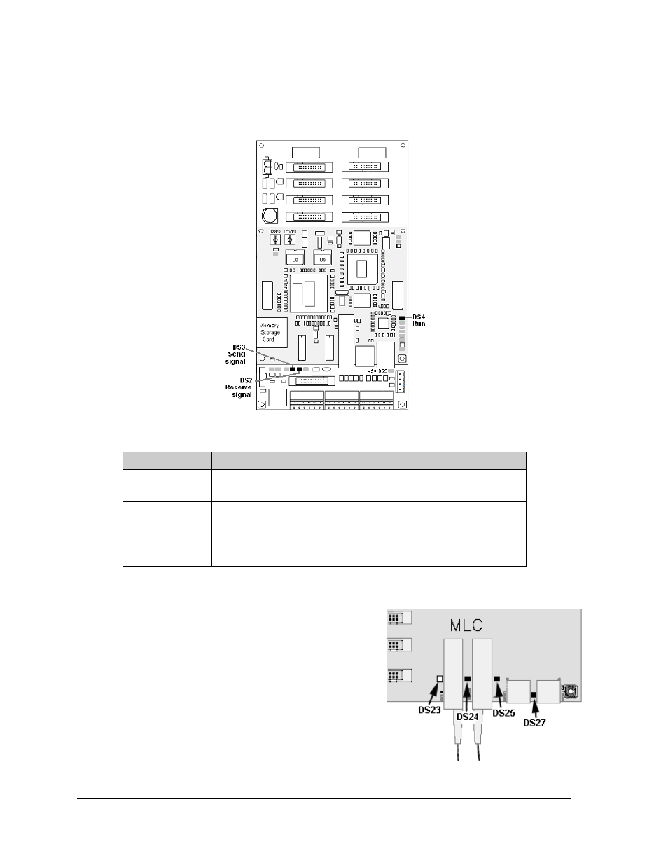
7.2 MLC
Diagnostics
Each MLC unit contains four red diagnostic LEDs.
When fiber is properly connected, the LED labeled
DS23 (left side) will be off and the other LEDs will be
on.
Figure 42: Controller Component Layout
Label
LED
Operation
Run
DS4
Steady FLASH about once per second indicates controller is working
properly.
Send
signal
DS3
OFF is the normal state. FLASH when transmitting communication to
the computer.
Receive
signal
DS2
OFF is the normal state. FLASH when receiving communication from
the computer.
Figure 43: MLC Diagnostic LEDs