Appendix c: rs/422 system (old signal converter) – Daktronics G-1000-34-R User Manual
Page 47
Appendix C
C-1
Appendix C: RS/422 System (Old Signal
Converter)
Daktronics is continually making improvements to our display systems in order to offer the highest quality
and latest technology in our products. This appendix covers the connections between the first display
and the Venus 1500 computer using the older signal converter.
Reference Drawings: System Riser Diagram (RS/422) . . . . . . . . . . . . . . . . . . Drawing A-88425
Signal/Power Termination Panel . . . . . . . . . . . . . . . . . Drawing A-88427
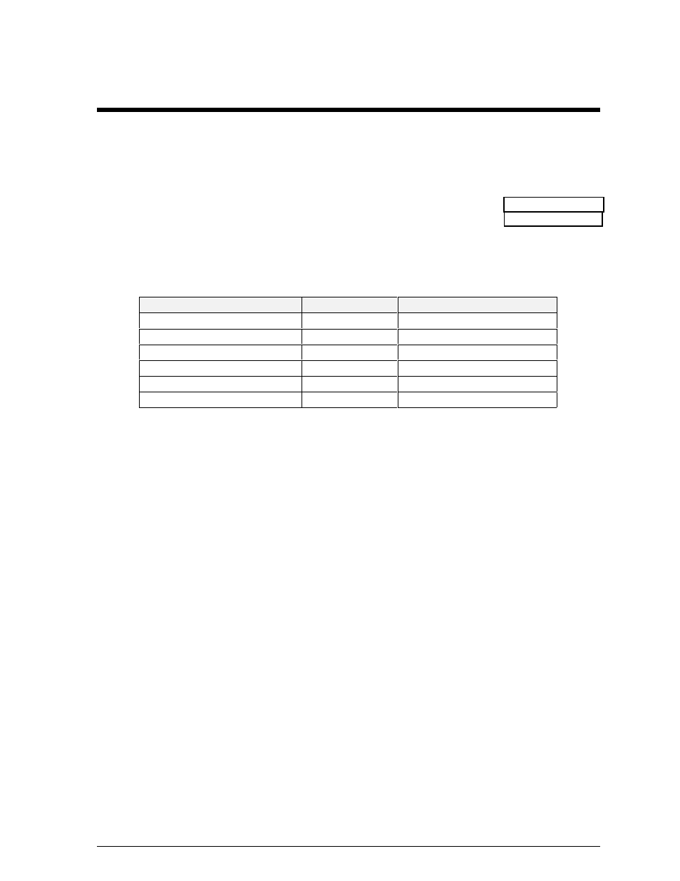
One end of the signal cable should be terminated to the 10 position terminal block labeled “DATA IN.”
Drawing A-88425 is an example of the termination panels. The other end is terminated at the signal
converter cable (Daktronics part number 0A-1137-0106) in the control room.
Pin No.
Field Cabling
Terminal Block (Data In)
Pin 1 (white) (Data TX-P)
White
Pin 4 (Data RX-P)
Pin 2 (blue) (Data TX-N)
Blue
Pin 5 (Data RX-N)
Pin 3 (green) (GND)
Green
Pin 6 (GND)
Pin 4 (black) (Data RX-P)
Black
Pin 2 (Data TX-P)
Pin 5 (brown) (Data RX-N)
Brown
Pin 3 (Data TX-N)
Pin 6 (red) (GND)
Red
Pin 1 (GND)