Chapter 2 – DFI COM100-B User Manual
Page 24
www.dfi.com
Chapter 2 Hardware Installation
24
Chapter 2
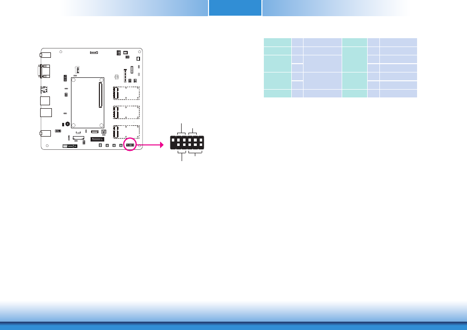
Front Panel Connector
HDD-LED - HDD LED
This LED will light when the hard drive is being accessed.
RESET SW - Reset Switch
This switch allows you to reboot without having to power off the system.
ATX-SW: ATX Power Switch
Depending on the setting in the BIOS setup, this switch is a “dual function power button” that
will allow your system to enter the Soft-Off or Suspend mode.
PWR-LED - Power/Standby LED
When the system’s power is on, this LED will light. When the system is in the S1 (POS - Power
On Suspend) state, it will blink every second. When the system is in the S3 (STR - Suspend To
RAM) state, it will blink every 4 seconds.
1
2
11
12
HDD-LED
RESET-SW
PWR-LED
ATX-SW
Pin Pin Assignment
Pin Pin Assignment
N.C.
1
N.C.
PWR-LED
2
LED Power
HDD-LED
3
HDD Power
Signal
4
LED Power
5
6
Signal
RESET SW
7
Ground
RST Signal
PWR-BTN
8
Signal
9
10
Ground
N.C.
11 N.C.
Key
12
Key
COM1
COM2
I C
COM2
COM1
Front
Panel