Chapter 2 – DFI COM101-BAT User Manual
Page 20
www.dfi .com
Chapter 2 Hardware Installation
20
Chapter 2
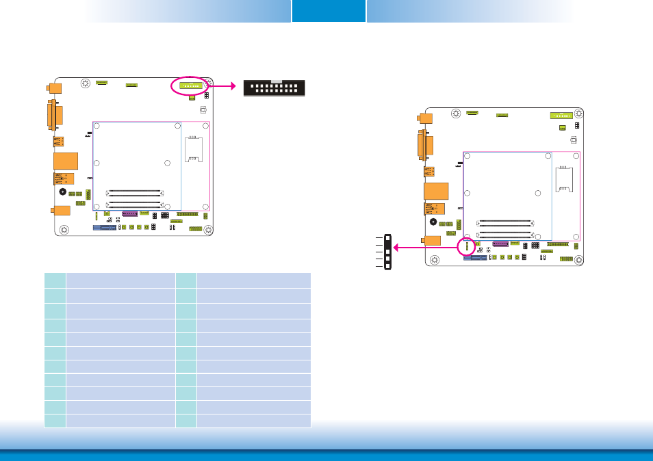
Digital I/O Connector
The 8-bit Digital I/O connector (4-bit GPI and 4-bit GPO) provides powering-on function to the
external device that is connected to the connector. The pin functions of the Digital I/O connec-
tor are listed below:
Pins
Pin Assignment
Pins
Pin Assignment
1
GND
2
+12V
3
DIO7 (GPO3)
4
+12V
5
DIO6 (GPO2)
6
GND
7
DIO5 (GPO1)
8
+5V
9
DIO4 (GPO0)
10
+5V
11
DIO3 (GPI3)
12
GND
13
DIO2 (GPI2)
14
+5V_Standby
15
DIO1 (GPI1)
16
+5V_Standby
17
DIO0 (GPI0)
18
GND
19
GND
19
1
2
Digital I/O
S/PDIF Connector
5
1
+5V
Key
SPDIF out
Ground
SPDIF in
S/PDIF
The S/PDIF connector is used to connect external S/PDIF ports. Your S/PDIF ports may be
mounted on a card-edge bracket. Install the card-edge bracket to an available slot at the rear
of the system chassis then connect the audio cable to the S/PDIF connector. Make sure pin 1
of the audio cable is aligned with pin 1 of the connector.