Chapter 2 - hardware installation, System board layout, System memory – DFI DL310-C226 User Manual
Page 9: Chapter 2 chapter 2 - hardware installation, Board layout, Rear i/o onboard i/o storage expansion, Chapter 2 hardware installation, Channel a - ddr3_1 and ddr3_2, Channel b - ddr3_3 and ddr3_4 • supports
www.dfi .com
9
Chapter 2 Hardware Installation
Chapter 2
Chapter 2 - Hardware Installation
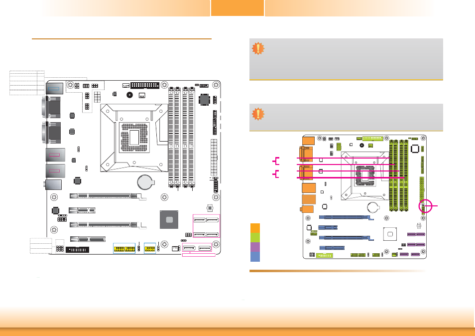
Board Layout
USB 2-3/6-7
Power Select
(JP8)
DDR3_1
DDR3_3
DDR3_4
DDR3_2
Socket LGA1150
Intel
C226
PS/2 KB/MS
USB 8-9
USB 2.0
LAN 1
USB 0-1
USB 3.0
LAN 2
USB 4-5
USB 3.0
1
USB 10-11
Power Select
(JP18)
1
1
SATA DOM
Power Select
(JP17)
1
Clear CMOS
Data (JP9)
1
SATA 1
1
SATA 0
1
SATA 3
1
SATA 2
1
System Fan 1
1
Chassis
intrusion
System Fan 2
1
Buzzer
SPI Flash
BIOS
COM2
COM1
Battery
1
2
9
10
1
2
9
10
USB 6-7
USB 2-3
1
2
9
10
USB 10-11
1
SATA 5
1
SATA 4
2
9
10
1
Front
Audio
1
ATX
Power
12
24
13
Power-on
Select (JP10)
Standby
Power LED
1
2
11
12
Front
Panel
DVI-I
HDMI
CPU Fan
1
1
USB 0-1 Power
Select (JP5)
USB 4-5 Power
Select (JP6)
+12V
Power
1 5
4 8
1
S/PDIF
DIO
1
2
19
1
1 1
(JP12)
(JP13)
(JP7)
DIO Power Select
(JP13)
DIO 11/13/15/17
Output State (JP7)
DIO 3/5/7/9
Output State (JP12)
Realtek
ALC886
ASMedia
ASM1442
ASMedia
ASM1442
Intel
WGI217LM
Intel
WGI210AT
Nuvoton
NCT6106D
1
PCIe x16 (x8 signal)
PCIe x16 (x8 signal)
PCIe x4
PCIe x1
6
5
2
1
LPC
12
1
11
2
1
2
25
26
Parallel
1
2
5
6
1
2
5
6
(JP11)
(JP2)
1
2
5
6
1
2
5
6
(JP14)
(JP3)
PS/2 KB/MS Power Select (JP1)
USB 8-9 Power Select (JP4)
COM1 RS232/422/485
Select
COM2 RS232/422/485
Select
COM1 RS232/Power
Select
COM2 RS232/Power
Select
(JP2)
(JP11)
(JP3)
(JP14)
1
1
(JP4)(JP1)
Line-in
Line-out
Mic-in
1
2
10
9
1
2
10
9
1
2
10
9
1
2
10
9
COM4
ISL95820
COM3
COM5
COM6
USB 2.0
USB 2.0
SATA 3.0
SATA 3.0
Note: SATA5 supports SATA DOM.
SMBus
1
System Memory
Standby
Power LED
Features
Important:
Electrostatic discharge (ESD) can damage your board, processor, disk drives, add-in
boards, and other components. Perform installation procedures at an ESD workstation
only. If such a station is not available, you can provide some ESD protection by wear-
ing an antistatic wrist strap and attaching it to a metal part of the system chassis. If
a wrist strap is unavailable, establish and maintain contact with the system chassis
throughout any procedures requiring ESD protection.
Important:
When the Standby Power LED lights red, it indicates that there is power on the
system board. Power-off the PC then unplug the power cord prior to installing any de-
vices. Failure to do so will cause severe damage to the motherboard and components.
Rear I/O
Onboard I/O
Storage
Expansion
DDR3-2
DDR3-1
DDR3-4
DDR3-3
Channel A
Channel B
•
The four DIMM sockets are divided into 2 channels:
Channel A - DDR3_1 and DDR3_2
Channel B - DDR3_3 and DDR3_4
• Supports
DDR3 1333/1600MHz
•
Supports dual channel memory interface
•
Supports up to 32GB system memory