Assembling the antenna to the ring – DH Satellite GIBRALTER IV MOUNT User Manual
Page 6
Assembling the Antenna to the Ring______________________
The mount should be assembled by this point. Now it is time to install the antenna. First, locate the 1/8"
pilot holes on the ring and antenna. One is located next to one of the 16 ½” holes in the dish and the other is
located on one of the 16 blocks next to ½” holes on the mount.
(NOTE: These holes do not line up with one
another, they are only to identify the alignment of the dish to the mount.)
Drop the mount down to a
birdbath position so when the antenna is put into the ring, it will resemble a large birdbath. When you have
located these two holes, use 6-8 people and pick up the dish and gently turn it over so the antenna is now
pointing to the sky. Lift the antenna by the edge, get it up above your heads, and walk in toward the bolt
holes. Walk it over and set it into the ring, making sure the pilot holes line up. Now slip in some 1/2" x 3”
bolts to hold it and keep it lined up with the mount holes until a worker can get into the dish. Before you
have a worker climb a ladder and get into the dish, please have one worker support the lip of the antenna
and mount before anyone gets into it. Have the smallest worker (installer) get into the dish and install the
bolts and feed assembly and hold them while they are tightened. Install the bolts as in Figure #6. DO NOT
OVER TIGHTEN. Install the back braces finger tight. Refer to Figure #7.
(
Instructions on page 5
)
Now align the 36" heavy duty actuator with the right side brackets on the back of the mount. See Figure #8
on page 5. First, assemble the actuator clamp and slide it about halfway down the actuator tube; tighten all
nuts. Take the 3/4" x 10" bolt and attach the clamp to the right side rear of the 4" tube on the top of the
base. Then take the eye bolt on the end of the actuator and put it between the right side brackets on the
framework of the ring. Use a 1/2" x 2" bolt and use a lock washer and nut to secure this in place. Now take
the stow bracket (refer to Figure #9 on page 5) and install thru the left brackets on the back of the base next
to the elevation arm, tighten the 3/4" nut.
(Insert spacer before tightening the ¾” nut, spacers are placed on the ¾” bolt
that holds the storm bar clamp.)
Slide the storm stow rod through the bracket making sure the end with the hole is up, slide this up until it
fits into the left hand brackets next to the elevation arm. Use the 1/2" x 2" bolt and tighten.
DO NOT
TIGHTEN THE BOLTS THAT SECURE THE STOW BRACKET TO THE STOW ROD.
This is done
only in case of high winds or severe weather. Once the storm stow rod is fastened down in anticipation of
bad weather.
YOU MUST REMEMBER TO LOOSEN BEFORE YOU RESUME OPERATION.
The
motor will burn out if you fail to loosen the stow kit.
The 36" actuator will give you approximately 60 degrees of elevation travel. By positioning the clamp on
the actuator tube you can determine where this 60 degrees is used, 0-60, 30-90 or anything in between. The
mount is designed to travel 0-90 degrees.
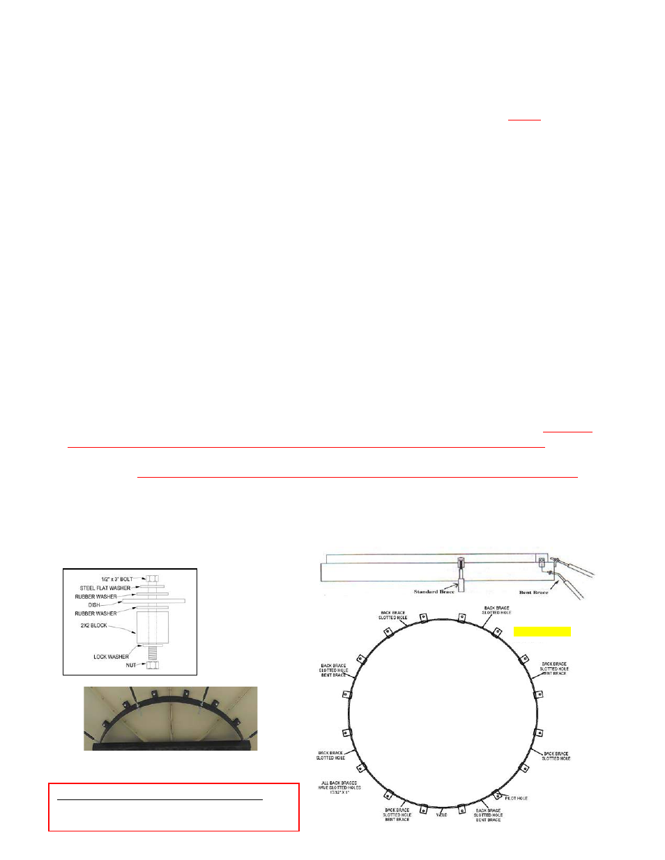
Figure #7 Back Brace To Clip
*FROM THE BACK VIEW OF ANTENNA
Pilot hole is located on the 2
nd
block from the left
of the weld on the ring.
Page 4
Figure #6
FRONT VIEW