Anatomy of the ad-24, Rear front – Digital Audio Labs Livemix AD-24 Analog Input Unit User Manual
Page 6
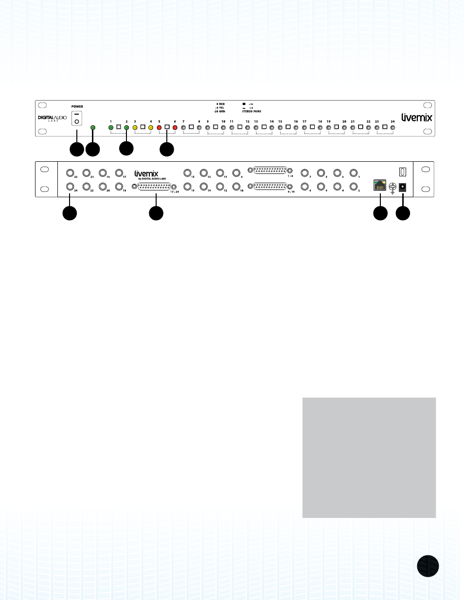
LIVEMIX AD-24
3
LIVEMIX
DATA
AD-24
12VDC
3.33A
LIVEMIX
DATA OUT
AD-24
2
8
5
6
1
7
3
4
REAR
FRONT
1.
EXTERNAL POWER SUPPLY CONNECTOR: Connect the included external power supply to this
jack. Make sure to only use the power supply that is supplied with your AD-24.
2.
POWER SWITCH: This switch turns on the power to the AD-24.
3.
¼” TRS INPUTS: These connectors accept a balanced or unbalanced line-level signal from your
analog audio source. Up to 24 separate audio channels can be fed to the AD-24, all of which are
available to your Livemix personal monitor mixers.
Whenever possible, we recommend using a balanced connection to the AD-24; balanced
connections allow for longer cable runs and offer better
interference rejection.
4.
DB-25 INPUTS: Each DB-25 connector carries eight
separate channels of balanced, +4dBu audio signals,
using a single multi-pin connector. Since each connector
carries eight channels of audio, connections can be made
more quickly (only three connections instead of 24). DB-25
connections can also be secured using screws available on
the connector.
The DB-25 connectors follow the TASCAM format. See
Appendix for more information on this wiring scheme.
ANATOMY OF THE AD-24
NOTE:
The DB-25 connectors on the
Livemix AD-24 are passed
through to the ¼” TRS inputs.
This means that you can
connect the DB-25 from your
mixer, and still use the TRS
jacks to connect the mixer
feed to another source.