Hitch coupler adjustment check, Hitch coupler adjustment – DR Power 33442 Tow Hitch Kit User Manual
Page 2
7 5 M E I G S R O A D , P . O . B O X 2 5 , V E R G E N N E S , V E R M O N T 0 5 4 9 1
©2013 Country Home Products, Inc. All rights reserved
334551
Figure 8
Lock Nut
Ball Clamp
Spring
Figure 7
Pull
Locking
Trigger
1/16"
Movement
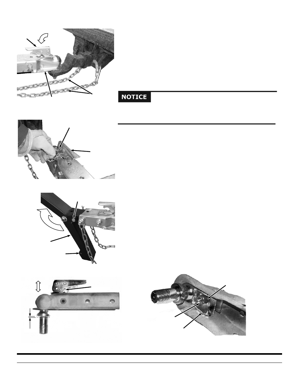
1. Close the Latch Assembly on the Tow Hitch Assembly to lock the Tow Hitch
Assembly onto the Tow Ball (Figure 4). Attach the towing Safety Chains to
the Tow Vehicle ensuring there is enough slack for turning.
2. Make sure the Hitch Coupler is properly and securely attached to the Tow
Ball.
3. Insert the Locking Pin into the hole of the Latch Assembly to lock it in the
closed position (Figure 5).
4. For extra safety and security, you may want to purchase a Lock to install into
the hole of the Latch Assembly.
5. Pull the Hitch Clip and Clevis Pin from the Support Leg and fold it up to the
transport position. Insert the Clevis Pin through the holes of the Leg and
over the top of the Tow Bar and secure with the Hitch Clip (Figure 6).
Hitch Coupler Adjustment Check
1. Place a 2" Ball in the Socket of the Coupler and close the Latch Assembly
(Figure 7). Verify that the Locking Trigger is properly engaged in its detent.
2. Pull on the Ball and/or Coupler, trying to remove the Ball from the Socket. If
the Ball moves more than 1/16" in the Coupler’s Socket, the Clamp requires
adjustment. Follow the proper adjustment procedure in the following steps.
Hitch Coupler Adjustment
1. With the proper size Ball in the Socket of the Hitch Coupler, close the Latch
of the Coupler completely (Figure 8). Verify that the Locking Trigger is
properly engaged in its detent.
2. Tighten the Locknut on the underside of the Coupler until the Spring
between the Nut and the Clamp is fully compressed. Then back off the
Locknut 1/2 turn or just enough that the Latch is able to Clamp and
unclamp from the Ball.
If you have any questions please contact us at www.DRpower.com or call 1-800-
DR-OWNER (376-9637) for assistance.
Figure 5
Latch
Assembly
Locking Pin
Figure 4
Tow Hitch
Assembly
Latch
Assembly
Safety
Chains
The folding Support Leg must be rotated up to the transport position when
towing the Log Splitter. Failure to properly secure the Leg up in the transport
position could damage the machine when towing.
Figure 6
Hitch Clip
and Clevis Pin
Support Leg
Transport
Hole