Connecting the panel heater, 2/ unlocking the panel heater’s hanging frame, 3/ fixing the hanging frame to the wall – Fenix SOLIUS User Manual
Page 9
9
2/
Unlocking the panel heater’s hanging frame
We recommend that you place the panel heater face down on the floor.
-
Take a flat-bladed screwdriver and lift the slider, taking care not to bend it
.
-
While keeping the sli-der raised, push the hanging frame towards the bottom of the heater to release the upper
brackets S2. We recommend that you wear protective gloves.
-
Swivel the hanging frame downwards on the lower brackets S1.
.
-
Remove the hanging frame.
.
3/
Fixing the hanging frame to the wall
-
Place the hanging frame on the floor against the wall. Locate drilling points A.
❼
-
Refit the hanging frame, lining up with drilling points A to find drilling points B (you can also use a level)
❽
.
- Drill the 4 holes and insert the wall plugs. Use suitable wall plugs when fitting on a specific support (e.g. plaster-
board wall
).
-
Position the hanging frame and screw it down.
4/
Connecting the panel heater
Connection rules and regulations
- The panel heater must be supplied with 230V single-phase current at 50Hz.
- The panel heater’s power supply must be directly connected to the main supply after the circuit breaker without
any intermediate switch.
- Panel heaters equipped with a socket can be connected to a wall socket.
- The panel heater’s power cable must be connected to the main supply via a connection box. In damp areas, such
as bathrooms and kitchens, the connection box must be installed at least 25cm above the floor.
- An Earth connection is prohibited. Do not connect the pilot wire (black wire) to Earth.
- The installation must be fitted with an all-pole cut-off switch with a contact opening distance of at least 3mm.
- If the power cable is damaged, it must only be replaced by an electrician.
- If you are using the pilot wire and it is protected by a 30mA differential (e.g.: bathroom use), the pilot wire’s power
supply must also be protected on this differential.
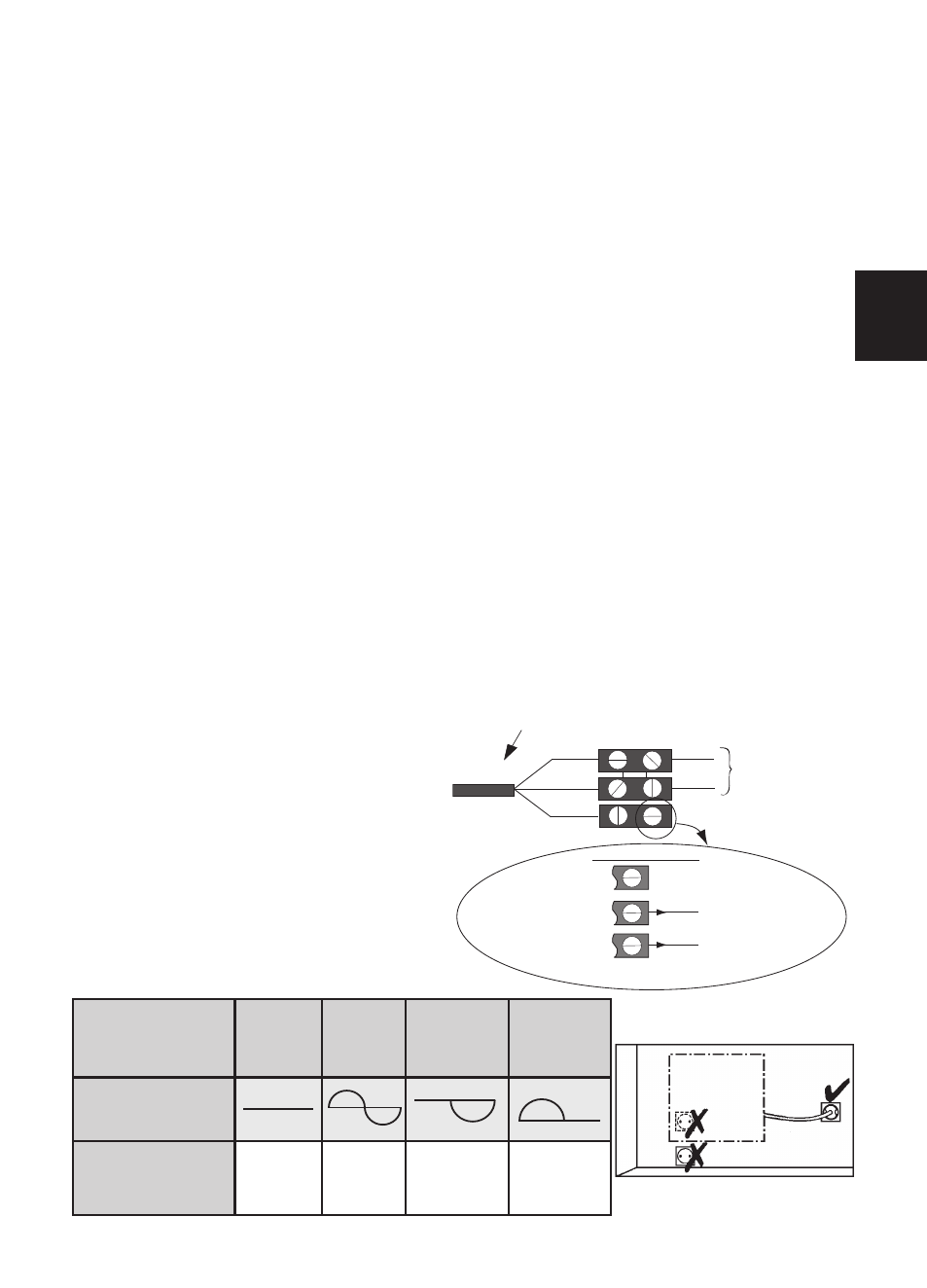
Wiring diagram for the heating panel
- Cut off the power supply and connect the wires as
shown in the following diagram:
- You can connect the pilot wire if your home is equip-
ped with a programming unit or controller.
In this case, make the following checks according
the selected mode (Comfort, Eco, etc.) to that the
programming instructions are being transmitted
correctly:
Panel heater cable
Phase=brown
Neutral=blue
PHASE
NEUTRAL
Electricity
grid
Three possible cases
Pilot wire=Black
1st case: only one heater
2nd case: Slave heater
3rd case: Master heater
The pilot wire end is insulated
and not further connected
To the appliance with cassette or
programming unit.
To pilot wire of an electronically
controlled appliance
COMFORT
ECO
FROST
SWITCH-OFF
OF HEATING
AND POWER
CUT-OFF
SIGNAL TO BE
TRANSMITTED
MEASUREMENT BET-
WEEN THE PILOT
WIRE AND NEUTRAL
0 Volt
230 Volt
-115 Volts
négative
+115 Volts
positive
GB