Planning for installation (cont.) installation – Fire Magic Deluxe Classic Series 42,000 BTU User Manual
Page 4
4
L-C2-017
REV 2 - 1406201000
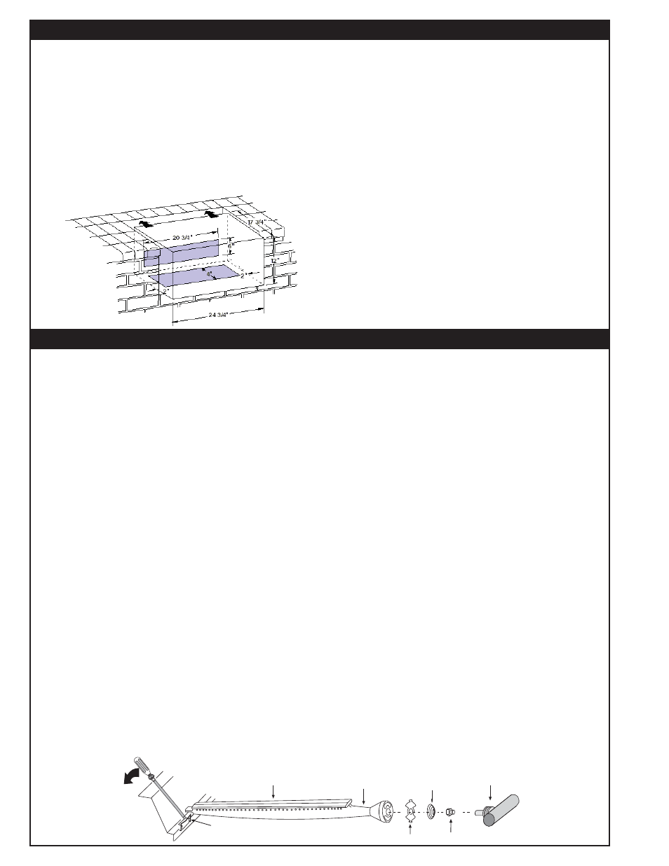
AIR SHUTTER
BURNER
MANIFOLD WITH
ORIFICE HOLDER
BURNER
ORIFICE
SPRING
BURNER NECK
BURNER CLIP
GAS SUPPLY PLUMBING REQUIREMENTS
Rigid
1
/
2
" or
3
/
4
" black steel pipe, or local code approved
pipe for temperatures up to 800°F (427°C), is required
to conduct the gas supply into the enclosure opening
for connection to the unit. Do not use a rubber hose
within the enclosure for the barbecue unit.
Apply only joint compounds that are resistant to all
gasses on all male pipe fi ttings. Make sure to tighten
every joint securely. Do not use pipe joint compound to
connect fl are fi ttings.
The gas supply pipe should enter from the rear wall of
the enclosure behind the barbecue unit, at least 2" from
either side, and between 2" and 8" above the fl oor as
illustrated by the shaded area in Figure 2.
If it is not possible to stub the gas line in from the back
of the enclosure, the connection may be made through
the fl oor at the rear of the enclosure. Install the gas line
stub at least 2" away from the side and back walls, but
within 6" of the back wall as illustrated by the shaded
area in Figure 2.
SAFETY NOTE: An external valve (with a removable
key) in the gas line is necessary for safety when your
barbecue is not in use. It also provides for convenient
maintenance and repair.
GAS SUPPLY AND MANIFOLD PRESSURES:
For Natural Gas - normal 7" water column, minimum
3 1/2", maximum 10-1/2".
For Propane Gas - normal 11" water column, minimum
8", maximum 13".
Perform the following checks before installing your Fire
Magic Deluxe Classic Barbecue:
1. CHECK FUEL ORIFICES FOR PROPER SIZE
a. Your Fire Magic Deluxe Classic Barbecue is equipped
with fuel orifices for natural gas, unless otherwise
indicated. To use with propane gas, you must install
smaller orifi ces to avoid hazardous overheating. The
proper orifi ce size for Natural Gas is #47 (drill size). The
proper orifi ce size for Propane Gas is #55 (drill size).
The size is stamped on the face of the orifi ce.
b. Remove the cooking grills, smoke oven and fl avor
grid from your barbecue.
c. If the gas supply has been connected, make sure the
burner valve is in the “OFF” position. Then carefully pull
the valve knob and rotary ignition knob from their stems.
Use a Phillips screwdriver to turn the face fastener
screws counterclockwise to release the face and remove
it from the barbecue. Make sure to retain the screws and
fi nish washers until you are ready to reattach the face.
d. Using a flat blade screwdriver, pry the burner
retaining clip from rear wall of the barbecue frame (see
Figure 4). Remove the burner by; A) Pulling it to the
front of the barbecue, B) Lift the far end out of the notch,
C) Pull the burner away from the manifold, taking care
not to lose air shutter and spring, which may become
detached when the burner is removed.
2. POSITION THE BURNERS FOR OPERATION
a. After checking orifi ce drill size install the air shutter
spring and the air shutter over the orifi ce holder fi tting,
between the burner and the pipe manifold, in the order
and position shown in Figure 3.
b. Replace the burners in the holding groove, ensuring
that the brass orifi ce and orifi ce holder fi ttings project
deeply into the burners. Replace the burner retaining
clips.
3. CONNECT THE GAS SUPPLY
a. You will need an CSA approved stainless steel fl ex
connector to bring the gas supply from the gas line stub
to the valve manifold. A 1/2" x 36" or 48" fl ex connector
with 1/2" fl are to 1/2" pipe adapter on one end, and a
1/2" fl are female fi tting on the other end is suitable for
most installations.
CAUTION: Use only stainless steel fl ex connectors
that are C.S.A. listed. A rubber or plastic connector
will rupture or leak, resulting in an explosion or
serious injury if used inside the barbecue enclosure.
b. Make sure that your gas supply is turned 'OFF'. Then
connect the 1/2" pipe adapter fi tting supplied with the
stainless steel fl ex connector to the gas supply stub.
Use pipe joint compound that is resistant to all gasses
on the male pipe fi tting and tighten securely. Do not use
pipe joint compound to connect the fl are fi ttings.
Figure 3 - Burner Orifi ce Diagram
Figure 2 - Gas Stub Diagram
PLANNING FOR INSTALLATION (cont.)
INSTALLATION